Stompy simulations, full scale test leg out for quote!

Ladies, Gentlemen, Undecided and Robots –

It’s been two weeks since our last update and the team has been cranking away…

We’ve been iterating through a design spiral trying to hammer out a leg design. Starting with rough estimates of masses and link lengths, the controls team figures out what kind of joint torques and range of motion would be required to meet the design goals and passes this information back the the mechanical team. The mechanical team takes this data to come up with a leg design, which they then run through FEA to determine the viability of the design. If they think it’s a viable design, they pass its critical parameters (masses, force/torque limits, actuator placements) back to the controls group, who plug the new parameters in to the simulation and give feedback back to the mechanical group, who modify the leg design, etc.

This is a labor intensive cycle that we’ve run through several times in the past 2 weeks and have come up with leg designs that we think will work. Without further ado, our first glimpse of Stompy walking…

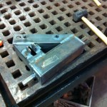
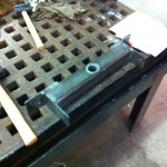
These legs are designed to be cut from sheet steel on a water jet. The waterjet cuts slots and tabs so the pieces of the structural elements will slot together like Ikea furniture. We will then weld over all the tabs to make extremely strong leg pieces with minimal machining on our part.

This is what our full-size prototype leg will look like extended.

The torques on these legs is tremendous… at the hip the torque is on the order of 14,000 foot pounds. The torques decrease in magnitude as you go further out on the leg, allowing for lighter construction. The yaw link (the little chunk of metal between the body and the thigh) is made of thicker sheet steel than the rest and ends up weighing about 70lbs. The thigh link is around 200lbs without the actuator attached. One of the comprimises we had to make in the design spiral was to shorten the legs… we simply couldn’t achieve the safety factors we wanted with the legs spread out as far as they were in the original concept art.

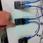
The prototype leg is out for quote at local machine shops, as is the next version of electronics, about which there will be a post soon. Also expect to see a Gimpy update!

~James

Design Your Own Joints

We kicked off today with a presentation about how to design simple hydraulic lever joints in a quantitative way. If you’ve ever wanted to design simple pivots powered by hydraulic cylinders, pneumatic cylinders, or any other type of linear actuator, check out this presentation for a solid introduction and no-nonsense design methodology.

How to design simple hydraulic joints

Other than that, today’s class was a huge work session. The controls team brainstormed about how to structure the code going forward before it became unmanageable, the electrical team debugged some gremlins that have been plaguing our Leg Cart encoders, and the mechanical team focused on laying out the components of the final chassis and designing a full-scale leg.

We’ve decided as a team that we need to build a full-scale prototype leg (and bolt it to a structural column for support…) to test both (a) our control of full-size pistons and (b) our manufacturing methodology at scale. We’ll be waterjet cutting a series of plates and welding the pieces together into box tubing like a giant jigsaw puzzle, and we want to make sure that we can pull that particular set of operations off at the Asylum in an efficient manner. We’ll still be using the Leg Cart powerplant to run it through its paces. Look forward to some views of a full scale leg by next week!

That’s all for tonight! Off to dream about terrifyingly large robots.

-Gui

Leg Cart Operational!

Hello again!

First things first – we now have a Sponsors page! We just finalized our first sponsorship agreement with HydroAir (a New England fluid power reseller and engineering company) and HydraForce (a leading manufacturer of cartridge valves and hydraulic controls systems); between the two companies, they will be providing us 21 proportional valves for the robot.

We’re ecstatic to announce that after working full-bore this past week, and after a couple of minor irritating hiccups, we managed to finish the Leg Cart mechanical and hydraulic assembly and turn it on for its first couple of tests. We made a compilation video of all the tests we ran on the 15th – check it out:

The sparks were flying on Tuesday because that giant motor you see bolted to the cart draws 330 amps continuously to spin that pump. We thought we could get away with smaller batteries (and cords) than necessary since we were only going to be running the robot for a short period of time, but we ran it a bit too long. Oops. We’re switching over to a bank of batteries and much heavier duty cord before we run the robot again.

You’ll notice some jerkiness in the initial motions of the leg – we believe this is equally due to (a) air in the lines and (b) jury-rigged control of the proportional valves.

We assembled all of the hydraulic components in place, and filled them with hydraulic oil as best we could. Unfortunately, since the reservoir level is below our valves and some of our pistons, air is easily trapped in place. The compression and expansion of this air contributes significantly to making the leg so springy. Tomorrow night, we’ll be “bleeding” the robot (a rather scary name for removing air from hydraulic lines) – we’ll be detaching all of the components, bringing them under the fluid level of the reservoir, and even assembling some of the components in a bath of hydraulic oil to make sure no air gets in. The big lesson learned for the real robot assembly is to place the reservoir higher up, the valves and pistons lower down, and make absolutely sure to fill the system in a way that removes as much air as possible beforehand.

Our control of the proportional valves for the test amounted to a box of switches attached to each of the valves, powered off of a current-controlled power supply. The more current you push into the valves, the more hydraulic flow the valves allow – you can check out the HydraForce valves we’re using here. We had no idea what current settings would work for the robot, which is why you see the robot start moving really quickly at the start of the film and then move in a much more controlled fashion later on.

Check out our gallery of hydraulic assembly pictures below for more details on how we built this thing!

That’s all for now. We’ll get some more videos once the electrical and controls team wrestles the mechanical system into something that’s much more behaved!

-Gui

Preliminary Leg Cart Assembly A Success!

Hello again!

Yesterday, I presented on the basics of hydraulic system assembly. While technically only the mechanical team would have to worry about such things, we present basic lessons to the group so everyone is on the same page. After that, the group split up, with the mechanical team going out to assemble the parts we had and the controls and electrical group discussing next steps to controlling the Leg Cart.

The mechanical team took all the parts that we had been slaving over for the past month and put them together in our first fit-up. Even though not all of the parts were done, or all of the features machined or welded in, this let us develop a list of to-dos to keep track of and fix before the final assembly this weekend. It also let us get a sense of how big the cart and leg really were… we’re both horrified and really excited to see the cart paddling itself around Artisan’s Asylum in the near future. Without further ado, I encourage you to check out the pictures of the fit-up below!


Just a reminder, the test leg is a roughly half-scale prototype we’re using to characterize the building blocks of our system. The leg isn’t anywhere close to the final design, it’s just a quick test system we could produce relatively quickly. The cart will hold a hydraulic power system in its base, consisting of a loaner 100-horsepower electric motor, our hydraulic pump, the fluid reservoir and all of other hydraulic system components. As if the system weren’t dangerous enough, we’re running the electric motor off of Adam Bercu’s electric motor cycle battery. Woohoo!

Also, in other news, we had our first team photo after the fit-up! Check it out here:


The Project Hexapod Team


Stay tuned for updates after this weekend, when we finish the mechanical assembly of the cart, start the hydraulic system assembly, and with any luck, hand the cart over to the electrical and control teams.

-Gui

Sunday Build Blitz was Great!

Today (Sunday May 6) was an epic build session at the Asylum… work started at 10am and finished around 9pm.  The shop was bustling with activity… machining, grinding, welding, soldering… the fabrication team really came together and was firing on all cylinders.

Almost all mechanical parts have been fabricated for the leg on cart.  Electrically we have working valve control and joint angle feedback.  Tomorrow (Monday) will be a flurry of assembly.

Just a reminder, the test leg is a roughly half-scale leg we’re using to characterize the building blocks of our system.


Controls Assignment 2 Solution

The controls team pulled it together at the last minute and submitted a solution to the problem of pushing the leg cart in a smooth, controlled fashion.  “Controlled” in this context means that it can’t lift itself off the ground and foot slippage has to be minimal.

The control code here is 100% student written, from the joint controllers to the kinematics to the trajectory generation.  Go team!

For reference, the dots are 1m apart.  The simulation makes it clear that we really need to watch out for reaction torques about the yaw axis (note that the whole cart twists itself… this is with a relatively realistic friction coefficient on the wheels).  We will probably want to look at this more closely before putting anything on hardware.

Stompy Is Coming

We came to a major decision this past week – the 2,500 pound, 135 horsepower, propane-fueled, hydraulically powered hexapod robot will be named… Stompy.

(It was a close thing, to be sure. We were split 10 to 8 between Stompy and Fluffy. Stompy seemed more unique and somehow more appropriate, though).

Today’s class was largely a workday. Dan gave a presentation on an introduction to controls systems and, specifically, the choices we’ve made thus far to ensure robust control of the hexapod. The controls group then chugged away at the Leg Cart simulation, while the mechanical group hit up the welding shop for a blitz of manufacturing. I think/hope we’re about a week away from assembling the full Cart, but we’ll see how it goes this weekend.

One big thing that got done – I finished the first round of concept art for the project. Given the parameters we’ve been working so far, the design techniques we’re aiming for, and the major components we’ve selected, I give you a first glimpse at Stompy:

Why? Because we can.

Note the two seats side by side. This is no solo ride.

You may be confused as to how large this robot is. The distance between the centers of the two middle legs, folks, is currently 17 feet. That’s about a lane of traffic… and a half. The bottom of the frame is over 6 feet off the ground. To give you an idea of how big that really is, check out this comparison to a shoddily rendered version of my car.

I promised myself my next car would have legs.

Stompy is coming, folks. Get ready.

Leg Cart Progress

Well, we just wrapped up our second class session. We kept lecture time pretty short – we only did a brief introductory presentation on steel weldments (which you can check out here) and reviewed a couple of homework assignments from the first class – and then spent most of the class on (a) prepping the controls team to work with the upcoming Leg Cart simulation and (b) coordinating the mechanical team’s build progress. James or Dan will post some simulation videos soon, but in the meantime I thought I’d show off some of the mechanical work.

To get started, let’s review the hardware we bought before class, starting with…

Our "new", 135 HP Toyota 2F engine
The pump and driveshaft that match the engine

One of the sets of decisions we made as instructors early on was deciding on the powerplant. We needed something that provided sufficient power to provide hydraulic fluid for a 1-2 ton robot, that was (a) robust, (b) relatively affordable, and (c) as off-the-shelf as possible. We decided to rip the hydraulic powerplant out of a forklift (specifically, a Toyota FGC-45 from 1991) and repurpose it. The net result is that we have a 135 horsepower, propane-powered powerplant that produces upwards of 35 gallons per minute of hydraulic fluid at 2,500 psi. The fact that it’s propane fired means the robot can operate for brief periods indoors, and also means that we can swap industrial-grade fuel tanks good for 6 hours of runtime without having to custom build or fill any of the fuel system components.

So that’s what we have – what we’re working on now is making the Leg Cart, our prototype hydraulics platform. The idea here is to make a platform on “rails” (i.e., only able to move in one dimension) that has a single leg and a hydraulic powerplant on board (we’re borrowing the pump from our full system and running it off of a giant electric motor). This will be the students’ introduction to hydraulic systems, so we’re building something small (relative to the final system – the cart will still be 600 pounds…) at first so we can screw up and figure out what we’re doing. Without further ado, here’s the progress we made on the cart chassis in the past week:

The Leg Cart chassis as of 4/26/2012

Spark and Mac have been working hard at it for the past week or two – good work guys! Next up, we have the base weldment for the arm pivot:

Base weldment progress as of 4/26/2012

Adam and Andy teamed up to work on this over the past week. Unfortunately, some material was backordered, but we’ll be resolving that shortly.

Joel, Joe, Mike and Jona are all working on parts that are heavy on machining and low on welding, so we’ll see updates from them a bit later on in the process.

That’s it for now. Keep an eye out for an update on simulations!

-Gui

All Systems Online

OK! The blog is up, we just had our second class session, metal’s being cut, and simulations are being written. We’re off to a hell of a start, and now it’s time to tell the world.

We are Project Hexapod. We’re a team of 19 people who are trying to pull off the highly improbable; building a giant (1-2 ton, 15 foot diameter), rideable 6-legged hydraulic robot. We’re not some robotics company, and we’re not working off of some big grant or another. We’re tackling this problem in a whole new way; we’re a class based out of Artisan’s Asylum, a community workshop with all the fabrication facilities we could possibly need, where 15 students are learning how to build robots from 3 industry roboticists from Barrett Technologies and other local robotics companies, and 1 national champion Battlebots builder as a teaching assistant.

As I mentioned, we just had our second class session. The class officially kicked off on April 17th, though me, James and Dan have been working on the system-level design for the past 6 months to make sure the whole thing was possible. We’re going to push to make this project as open-source, publicly engaging and widely available as possible, so be sure to check this blog for presentations, source code, design documentation, the works.

And thus, without further ado, let’s talk classes!

Class 1: What Did We Get Ourselves Into?

Our first class was all about shock, awe, and expectation management. We introduced ourselves, the scope of the project, the exercises and design steps we would be taking to achieve our goals, and then did a quick introduction to hydraulic systems to get everyone on the same page. Once all of the lecturing was done, we broke up into a controls team and a mechanical team; the controls team busied themselves in setting up a simulation environment that James and Dan developed for the class, and the mechanical team got launched on making and welding parts together for the Leg Cart (more on that in a bit). You can check out our introductory presentation here: Rideable Hexapod Intro 2012-04-17

After the introductory presentation, I presented an introduction to hydraulic systems. If you’ve never used hydraulics before, I suggest checking this out – they’re a fascinating power transmission technology widely used in farming equipment, earthmoving equipment and high end robots like BigDog, but are almost nonexistent in the hobby/amateur robotics world. There’s certainly a steep learning curve to hydraulics, but hydraulic systems are awesome and you should learn how to use them. Learn more about them with us here: Intro to Hydraulics 2012-04-17 (Warning! There is one gory image of a hand after it’s been hit by a hydraulic leak, which may be NSFW)

Once all the presentations were over, it was time to start work on the Leg Cart! Also known as the Land Barge, Land Gondola, single leg prototype, that-which-cannot-be-stored-easily, and generally-terrible-idea. The mechanical team got a giant cut list to work on for the next two weeks, and the controls team got introductory exercises in our custom simulation environment.

The Leg Cart

The cart is a giant, 600 pound monstrosity with a half-scale hydraulic leg sticking out the side, a hydraulic power system (using a 100 pound field-wound electric motor attached to our hydraulic pump), all on four fixed casters (yeah… you heard us… we’re going full stupid here). The idea here is to have the students get familiar with working and welding steel, assemble  a functional hydraulics system for the first time, wire real hardware with feedback sensors and a computational platform, wrap feedback loops around sensors and the hodge-podge hydraulics system we’ve assembled, and then control custom hydraulics hardware in closed-loop forward and inverse kinematics. If everything goes according to plan, the cart will be able to paddle its way up and down a section of the shop aisle.

OK. That’s the update for class 1. Stay tuned for the next class update, where we post some pictures about our progress on the Leg Cart and maybe a simulation video or two!

-Gui