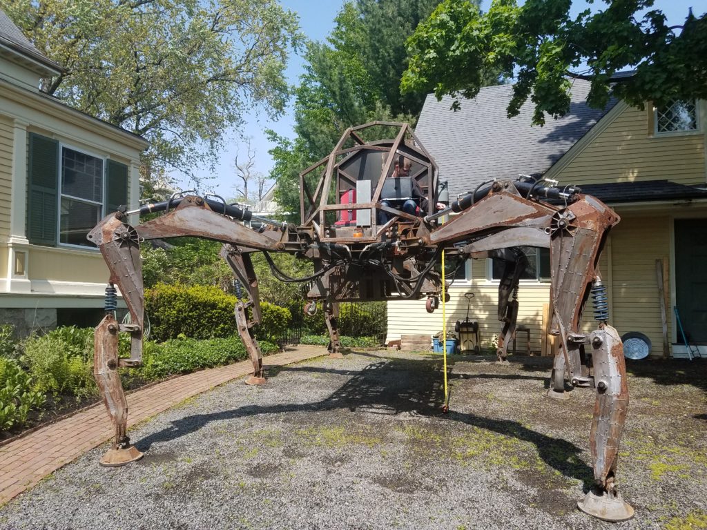
Our training wheels support dollies have stayed attached to Stompy for most of the standing and walking we’ve done so far. They keep the fragile underside of Stompy safe from hitting the ground but limit the types of things we can walk over.
We’re getting confident enough with the system to stand without the dollies.
This allowed us to finally test if we can safely go belly down.
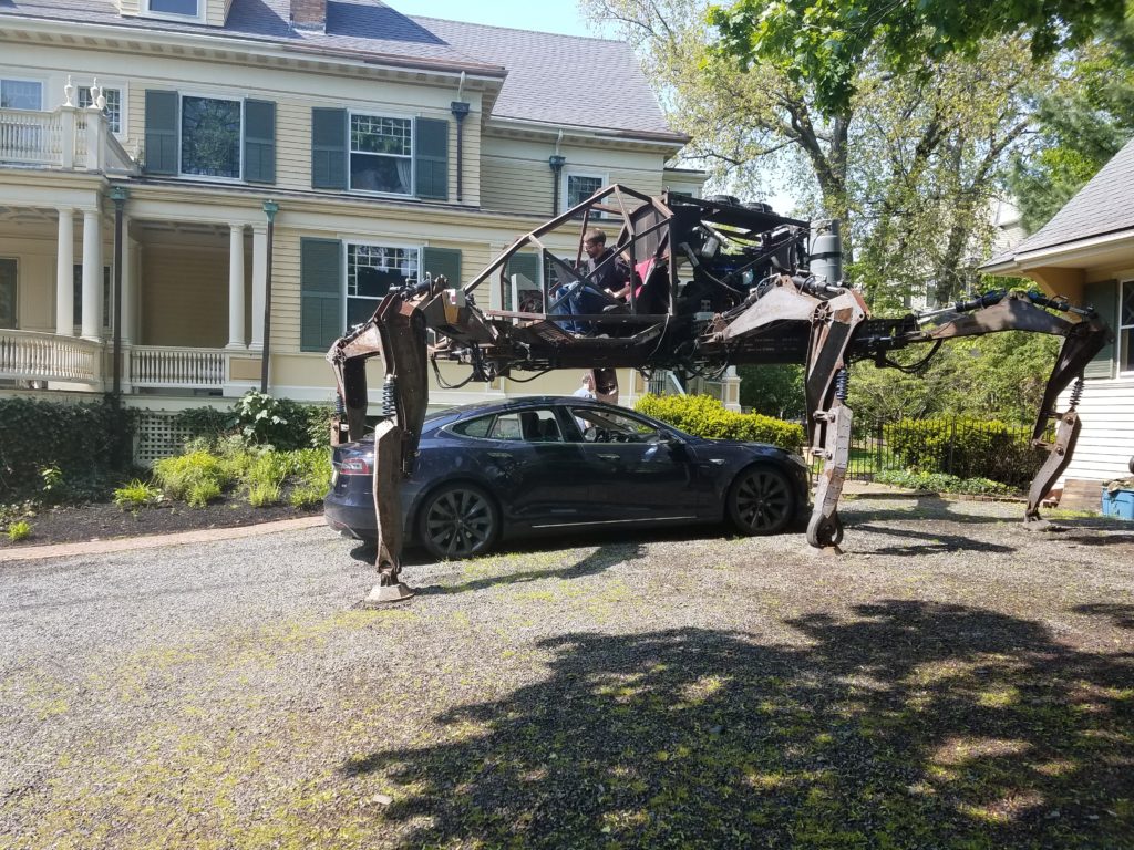
Shedding the dollies has the extra benefit of opening up a much needed new parking spot.
Although we haven’t been great at updating the website we have continued to toil away on the robot. We’ve fixed hydraulic issues, engine problems, electronics revisions and software bugs. Up to this point we’ve taught our baby robot to stand and toddle stomp around.
We’re excited to be at this stage of the project. If you are one of the generous (and patient) souls who donated in the “will it stomp” tier of our kickstarter we will be reaching out shortly to start the process of getting things to stomp!
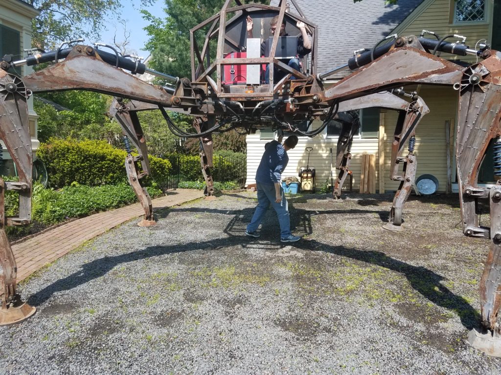
The other day Brett and Joel got a foot on the robot to move in a straight line! This required coordination of multiple joints and path planning.
They used the Arduino Teensy board that Joel developed as the leg controller, talking to a computer running some python code that Brett wrote to do path planning and kinematics.
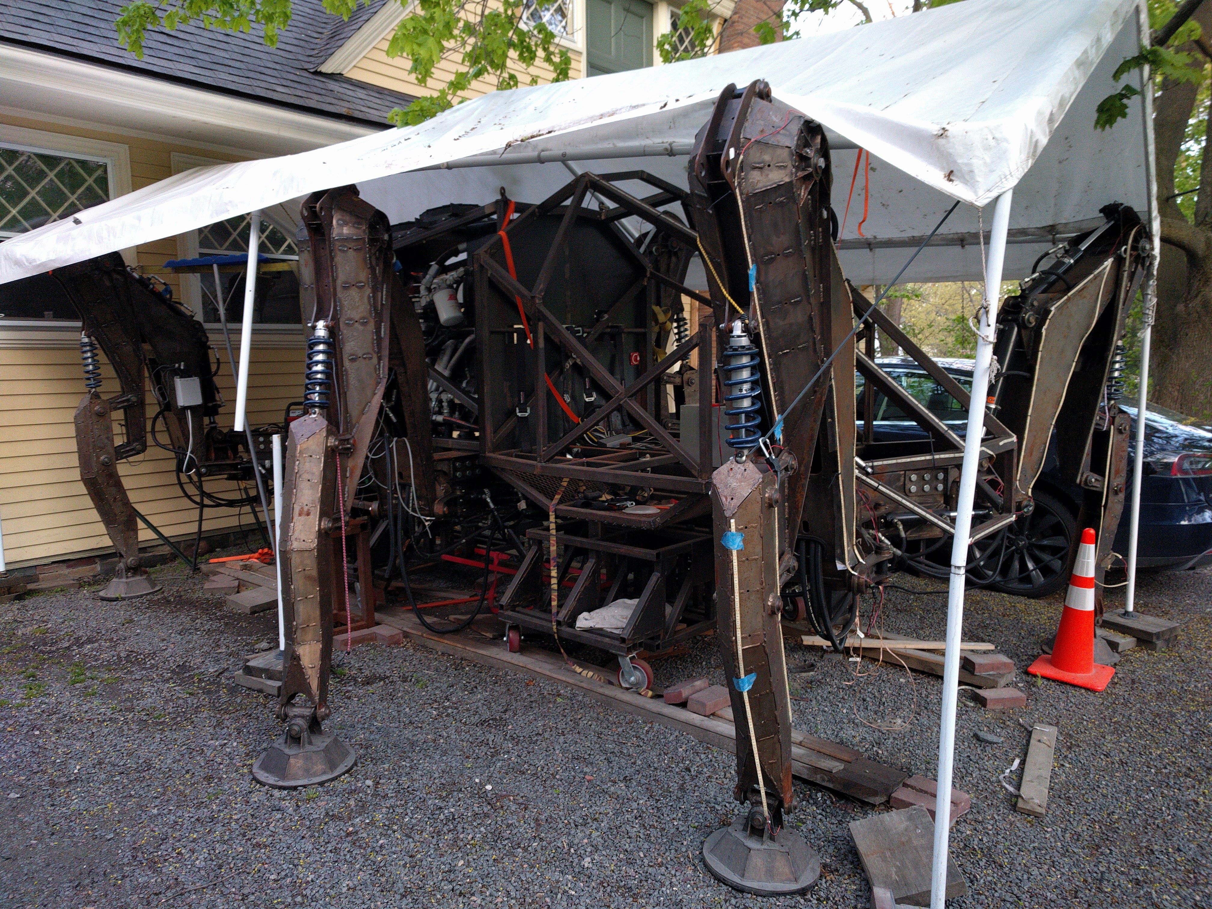
Stompy is built! There are six legs, a chassis, a roll cage, and an engine. The engine runs and powers the hydraulics. All of the hydraulics are hooked up and working properly.
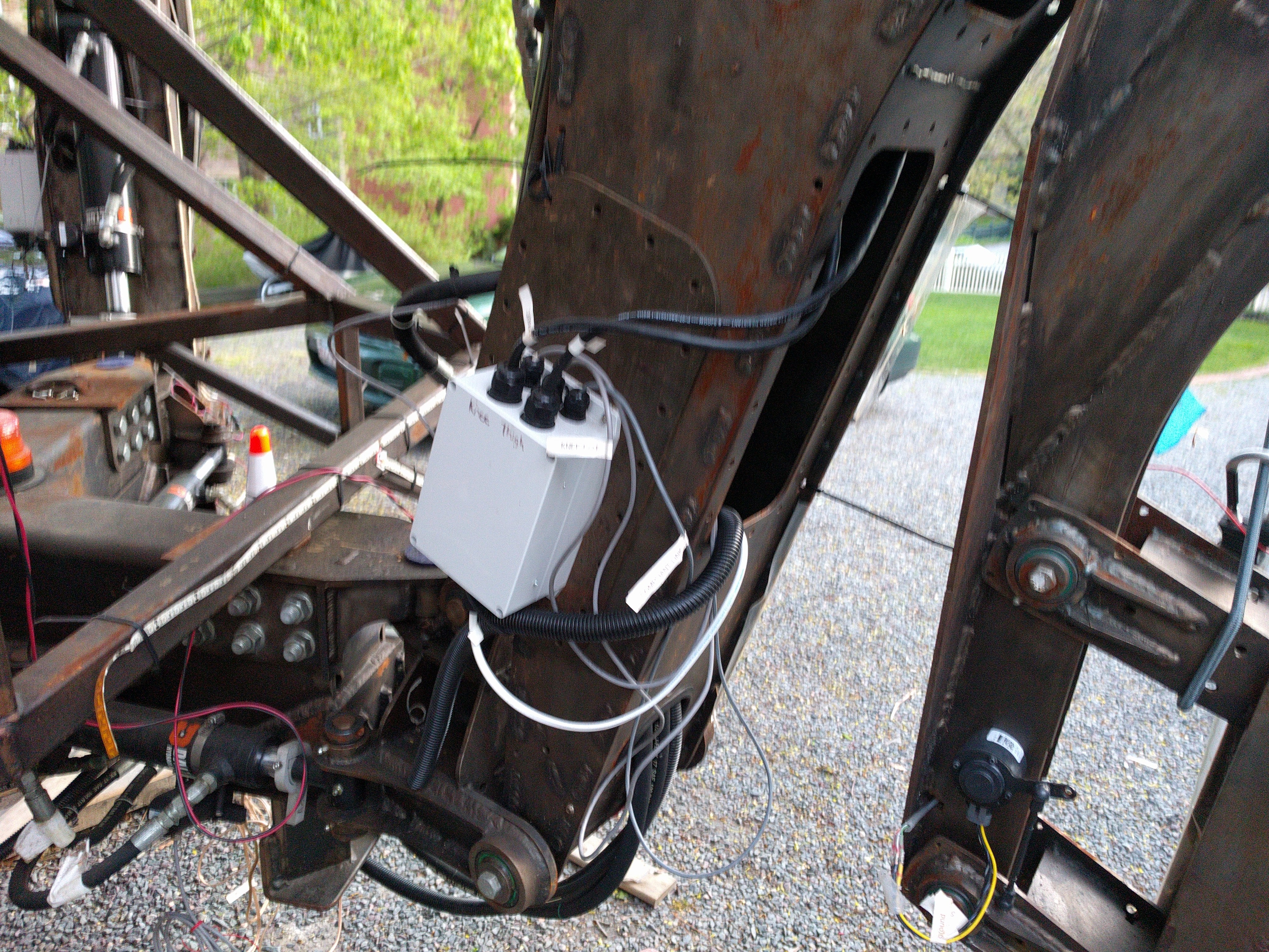
There is still some work left to be done on the electronics. All six legs have a sealed Leg Controller enclosure with a Beaglebone Black inside. The Beaglebones have custom perf board capes. Each cape carries a Dual MC33926 Motor Controller, which can drive four PWM channels to control two pistons. The current plan is to drive the Knee and Thigh joints with those two channels, and add three more boxes located on the chassis to drive the Thigh joints.
All of the Leg Controller boxes are wired up to the network switch. We can plug a laptop into the switch and talk to all the Beaglebones in the legs.
The Beaglebones don’t have software to do closed loop control yet, but we can SSH in and directly set the PWM outputs to move the Knee and Thigh joints.
Software
Most of our activity right now is focused on software. We recently decided to run our code in ROS and have been spending a lot of time getting the ROS ecosystem up and running.
We have a SDF file that Brett Graham put together a little while back. He even linked in the Solidworks files for the robot, so we’ll be able to simulate a realistic model of Stompy in Gazebo.
Current Tasks
Seth Woodworth and Robin Garner have been working on using Vagrant and Ansible to automate building virtual environments. The goal is to be able to repeatably spin up a virtual machine with the ROS environment set up that we can use for development. Hopefully we will be able to use the same Ansible setup to deploy directly to the Beaglebones on the robot.
Spark is working on getting a launcher script to run nodes on different machines across a network.
Chris Stokes has been investigating the SeeedStudio Motor Bridge Cape as a new option for a motor controller cape. If we switched over to it, it would replace the custom perf board capes as well as the MC33926 motor controllers. This option would allow us to control all three leg joints from the Leg Controller BeagleBone. There are pros and cons to running all three leg joints from the Leg Controller, but overall it’s probably preferable to do it if we can.
Here are some more photos, and a video showing the constructed robot.
Hello everyone! We want to take a moment and catch all of you up with how the build process has been developing over the past few months. As a quick note – we’re most active on Facebook, so if you’d like weekly photo albums of what we’ve been up to, we suggest “Liking” us there!
In our last post, you saw us put out a call for new members; we’re happy to report that we accepted 8 new people onto the team, and we’ve all been putting our heads down and cranking on steel fabrication. We’ve been building our way up the robot’s leg in parallel (i.e., we’re building all of one type of part before moving on to the next) from the calves, to the knees, to the thighs, and we’re on the cusp of starting the hip – the final link in the chain. We’re building 8 copies of each piece, with the hope that in the best case, we have two spares, and in the worst case, we can mess up 2 parts of each type without affecting the overall construction schedule. After the hips are done, we’ll start the chassis build in earnest, and then we’ll be ready for final assembly! We’re going to take a moment and step through what our build process has looked like, and how it’s evolved as we’ve gotten better at large-scale steel fabrication.
All of our leg parts are made out of pieces cut on the CNC plasma cutter we assembled at Artisan’s Asylum. The plasma cutter has a couple of big advantages – it has very low running costs, it’s extremely fast, and it’s available on an as-needed basis. Check out this album for some shots of the plasma cutter in action, and a look at what we have to do to move some of our heavier sheets around:
%%wppa%%
%%slide=13%%
The plasma cutter does have some distinct disadvantages, though – the biggest being that plasma cut parts require a lot of cleanup before they can be reliably welded together. The plasma cutting process creates what’s known as dross on the back side of cut parts. This is a thin, brittle, very hard layer of flash-frozen steel that usually has to be removed with grinders. We performed some initial experiments which indicated we couldn’t create reliable, clean welds if the dross and mill scale on our steel plates was still present, so we set up an assembly line of angle grinders to clean up all of our plates. After dozens of hours of grinding, we realized that we desperately needed another way to clean parts or we’d never finish; we then switched to pickling, a process where parts are dipped in vats of acid to remove impurities. We started with hydrochloric acid, and then quickly switched to citric acid due to safety and cost concerns. Check out the cleaning processes we’ve been through in this album:
%%wppa%%
%%slide=14%%
Once parts have been cut and cleaned, it’s time to assemble the pieces into cohesive links and weld them together. All of our links fit together like 3D jigsaw pieces; plates fit together with slots and tabs (check out our “Anatomy of a Thigh Link” post for an example section from our prototype leg), and square nuts and button head cap screws hold the plates together after they’ve been fit-up. This means that our leg sections are self-jigging and self-aligning, and require very little external tooling to fit together precisely. Once assembled with screws and square nuts, the links can be moved around for transportation and weld positioning. After assembling, we tack weld them in a specific order, plug weld sections together to increase the rigidity of the assembly, and finally weld all of the seams together to finish the parts.
%%wppa%%
%%slide=15%%
Once the leg sections are assembled and welded, it’s time to add joint bushings. In our prototype leg assembly, we made joint pivots and hydraulic cylinder pin joints with bronze bushings and carefully-aligned and welded steel cylinders that spanned the width of our leg sections. This style of design was incredibly time-consuming to weld accurately, and more often than not resulted in significant post-machining steps like hand reaming that gave relatively poor results across the width of our legs. We decided to cut down significantly on assembly time and fabrication time by switching from bronze bushings to self-aligning spherical bushings – that way, even if we were a little off during fabrication, jointed assemblies would still fit together relatively seamlessly. Check out this album of our process for making bushing bosses and welding them on to our assemblies accurately:
%%wppa%%
%%slide=16%%
All that said, we now have a full robot’s set of thighs, knees, calves, and compliant links welded together. Pieces still need some finishing work before they’re 100% done, but most of the link segments are there. Now, it’s time to move on to making hip sections and the chassis, so that we can start final assembly!
We built custom stock racks to handle all of the robot pieces we've made. The calf pieces are stacked on yet another cart.
Also, one final bit of good news – we’ve received our custom cylinders from Dalton Hydraulics! We ordered these two months ago, and asked for a custom build so that we could have exactly the output ports we wanted on all cylinders (-08 SAE, to match our valves) and very tight tolerances on the cross tubes on the front and back of the cylinders so that we have as little backlash in our joints as possible.
Our order of 18 custom hydraulic cylinders from Dalton, with tight-tolerance crosstubes and SAE -08 ports.
That’s it for now – look for thigh links next, and the start of chassis construction!
Hi everyone! We just wanted to say that we’ve moved out of our design and prototyping phase, and into our build phase! Now that we’re fabricating, we’ve decided to expand the team to include new skilled steel fabricators; if you’re in the Boston area and are interested in joining us, check out the call for new members at the bottom of this update, or check out the application survey here. Now, on to updates!
At the start of the year, we worked pretty hard to build out both the hydraulic powerplant for the final robot and a CNC Plasma Cutter (that would then be used to cut parts out for the robot’s legs and chassis). Both items took us awhile to complete, and took more energy than we were hoping, but we wrapped them up around May. Since then, we’ve been working hard to finalize our leg design, get the links analyzed for overall strength and manufacturability, and create manufacturing and quality control processes from scratch to ensure that we build as robust a robot as we can. If you’re interested, you can check out an example of the kinds of work instructions and processes we’re creating here.
We’re kicking off our triumphant return to communication with a recap of what’s been going on with the Hexapod design process. Today’s recap topic is the most visible change to date: the new leg design.
It’s happened again… we have failed to keep posting updates in a timely manner. Many apologies. I’ll try to catch us up a bit:
On the control side, there was a huge amount of progress in April. The system is a huge challenge to control. Keep in mind that in the testing below, we are moving at roughly the maximum speed allowed by our electric lab pumps. When running off the real HPU, the leg can move about twice the speed.
On the mechanical front, final leg design and FEA is in progress. Many of the shortcomings of the prototype leg are being addressed, including: Continue reading Update 5/21/2013
Our biggest update from this week is that we’ve just been sponsored by Tompkins Industries! Literally 15 seconds before we were about to place a giant order for hoses and fittings to finish our power unit, Tompkins Industries showed up and asked how they can help. Tompkins is a global suppliers of hydraulic adapters and fittings (among many other components) with 99% same-day fulfillment from stock, and are the perfect partners to work with for this phase of the project. Thanks Tompkins!
We worked with Tompkins Industries to get hydraulic fittings and hoses in-house to complete the power unit, and spent our week doing hydraulic assembly. In this update, we’ll show you our progress so far, explain a little bit more about the hydraulic system, and teach you how to assemble hydraulic fittings into a working system. Check it all out here:
Next week, we’ll be working on finishing some modifications to the structure of the power unit to attach batteries, accumulator mounting brackets, and lift points, and we’ll also be testing the prototype leg with the new orifice-reduction fittings James mentioned in his last post. We’re now waiting on some specialty hydraulic parts to finish off the power unit, but once those parts arrive, we’ll be ready to test the unit for the first time!
I’m going to detail a subtle problem we hinted at a few months ago. To understand the problem one needs a basic understanding of the system layout and a few key concepts, so I will quickly review.