Gui Cavalcanti received a General Engineering degree with a Robotics concentration from the Olin College of Engineering. He worked as a robotics engineer and systems integrator at Boston Dynamics, working on cutting edge mechanical design and systems integration for highly dynamic legged robots like BigDog, AlphaDog, and PETMAN. He was the Systems Integrator for the LS3 project, coordinating the joint engineering and development of multiple subcontractors and engineers. Over the course of his career he has also developed the mechanical systems for a robotic tuna, several robotic snakes, an ornithopter, and several other robotic animals. In his spare time he builds ridiculous things with ridiculous people, like a flotilla of SUV-sized rubber duck boats to take on the water on the 4th of July.
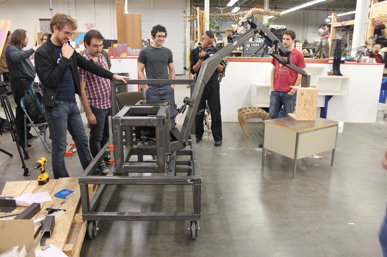
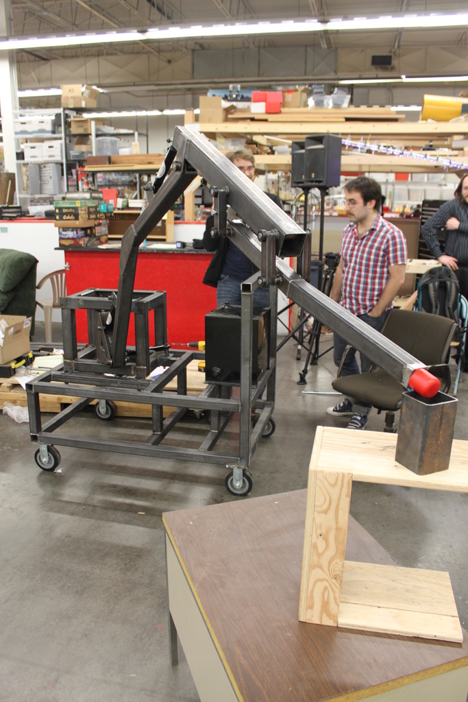
After months of fabrication, debugging, testing, more fabrication, and yet more debugging, we’re happy to announce that the leg cart rows itself right along! Check this out:
We have full inverse kinematic control of the test leg, and can get it to move the 600-pound cart in a straight line. The only catch, of course, is that we have to wheel the battery cart along behind the robot – hilarious shenanigans ensued. Next time, longer wires…
It’s still a little bit shaky, but we’re calling this good enough for now and moving on to the full-size prototype leg. We’re pretty sure our pistons on the test leg generate maximum forces that result in relatively low accelerations of our legs (the yaw piston produces around 800 pounds of force, to move a 150 pound leg), which is why everything’s so wobbly. We’re also pretty sure that slapping pistons that generate 12,000 to 18,000 pounds of force on 350-pound legs will take most of that wobble RIGHT OUT.
Now, on to the full size leg and Stompy!
Keep an eye out for my next update on how our full-size legs are designed.
So in case you didn’t know, we’re building Stompy, a 4,000 pound, propane-powered, 6-legged hydraulic walking robot that seats two. We’re about to put out a call to fundraise for the final robot via Kickstarter, and we want to have really awesome stuff to give away. If this doesn’t call for some cool logos, T-shirts and bumper stickers, we don’t know what does.
We, unfortunately, are all engineers, and those particular kinds of design skills have atrophied over the years, if they ever existed.
Thus, we introduce the Project Hexapod Swag Design Contest!
We would like designs for the following:
1. A bumper sticker. This is the reward for the first Kickstarter level, where you declare your undying love for giant robots by vandalizing nearby surfaces with adhesive-backed paper.
2. A supporter T-shirt. This is the shirt you get at one of the low-to-medium Kickstarter levels that screams “A bunch of nutjobs up in Boston have built a giant, life-endangering walking robot, and it’s so amazingly cool I bought this shirt to support them.”
3. A team T-shirt. This is the shirt that the 19 robot builders get to wear to fairs, job interviews, first dates, etc. It has to say “I build giant, life-endangering robots for fun, and if you have to ask why you wouldn’t understand the answer.” We’re looking for a comical front design here; the back would be designed later to include sponsor logos, team member names, and other shout-outs.
For those designs, we are putting up the following prizes:
1. A $100 prize for winning a category (up to $300 for winning all 3)
2. A free ride on the finished Stompy robot
3. If you win all 3 categories, free driver training on the Stompy robot instead of a ride
Both T-shirts are restricted to 4 colors or less so that they can be silkscreened cheaply; the bumper sticker will be digitally printed, and can be whatever colors you want. The supporter T-shirt will be one-sided – you choose whether it’s the front or back. Entrants (except for the bumper sticker) must be capable of producing color-separated files that could be sent to a screenprinter. Upon submitting a design to the contest, you grant Project Hexapod a non-exclusive license to it for the indefinite future.
We would like the swag to be comically self-aware of how large, dangerous, and awesome this project is, all wrapped up into one design. Significant bonus points will be awarded for catchy slogans, cartoonish depictions, and humor. Ideally, a conceptual Stompy would be pictured in part or in whole, in a way that we could make into a logo.
Enter the contest by emailing rideablehexapod@gmail.com with the subject line “Swag Design Contest -” followed by “Bumper Sticker”, “Supporter T-Shirt”, or “Team T-Shirt”. Attach your image files to the message, along with any description you think is necessary. In your email, indicate if you are willing to modify the design given feedback or not. Enter as many different designs (in separate emails) as you’d like!
All entries must be received by noon on Friday, July 20th. Entries will be voted on by the Project Hexapod team, and winners will be notified by the following Wednesday.
Here’s some art from our most recent development to spur some creativity:
These are our legs at a slightly older stage of development, on the concept chassis
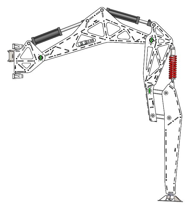
This is a comparison of our Gimpy leg to our full-size prototype leg.
This is what Stompy looks like relative to Dan, from the side.
This is what Stompy looks like relative to Dan, from the front.
This is what our full-size prototype leg will look like retracted.
This is what our full-size prototype leg will look like extended.
We kicked off today with a presentation about how to design simple hydraulic lever joints in a quantitative way. If you’ve ever wanted to design simple pivots powered by hydraulic cylinders, pneumatic cylinders, or any other type of linear actuator, check out this presentation for a solid introduction and no-nonsense design methodology.
How to design simple hydraulic joints
Other than that, today’s class was a huge work session. The controls team brainstormed about how to structure the code going forward before it became unmanageable, the electrical team debugged some gremlins that have been plaguing our Leg Cart encoders, and the mechanical team focused on laying out the components of the final chassis and designing a full-scale leg.
We’ve decided as a team that we need to build a full-scale prototype leg (and bolt it to a structural column for support…) to test both (a) our control of full-size pistons and (b) our manufacturing methodology at scale. We’ll be waterjet cutting a series of plates and welding the pieces together into box tubing like a giant jigsaw puzzle, and we want to make sure that we can pull that particular set of operations off at the Asylum in an efficient manner. We’ll still be using the Leg Cart powerplant to run it through its paces. Look forward to some views of a full scale leg by next week!
That’s all for tonight! Off to dream about terrifyingly large robots.
Apologies for the lapse in our updating – we’ve been in three solid weeks of Systems Integration Hell with the Leg Cart, trying to get our hydraulic system to achieve good position control on the hydraulic actuators. Because we’re purposefully developing with really low-end technology, we keep running into components that just don’t cut it – so slowly but surely, as we replace the components that just don’t cut it and upgrade the system, we’re building up a solid hydraulic powerplant. James will post a video of the position control we’ve managed so far a little later, but for now I want to talk about our hydraulic system.
So, this was our first pass at a layout for a low-cost (relatively – it still cost between $1,500 and $2,000 for all the components you see here), prototype hydraulic powerplant:
Our initial prototype hydraulic system
The central idea was to use a giant electric motor to spin up a gear pump while we work on getting our propane powerplant up and running. Because a gear pump displaces a fixed amount of fluid every rotation (and because there’s no guarantee that any pistons are moving while the motor is on), that fluid needs to go somewhere. The standard answer for a low-cost hydraulic system is to insert a relief valve on the pressure line; the relief valve allows pressure to build up to a set point, then the valve opens and dumps any remaining fluid into another set of lines. In this case, we dumped all of our remaining fluid into our return pressure line. Because the line was connected directly to our reservoir, the return fluid was at atmospheric pressure. We used the following components to create this system:
This version of the Leg Cart system didn’t last for too long. The reservoir kept the return pressure at atmospheric pressure, and that meant that the knee cylinder (which was above the oil level in the reservoir) was constantly full of air – we’re talking a couple of inches of piston movement worth of air, at all times. Once we understood exactly how much air was in the lines, we knew we needed to increase the pressure on the return side so that return fluid would force its way through the entire system. We did that by modifying our hydraulic system like this:
First upgrade to the Leg Cart hydraulic system
We added a check valve that had a cracking pressure of 65 psi to the return line, right before the filter. This meant that no return fluid would flow into the reservoir unless the return line was at or above 65 psi. While adding a check valve to increase return line pressure isn’t something I had seen done before, I figured it might work, and would be the cheapest solution.
This system successfully removed a lot (though not all) of the air from our lines. When we ran our joints through their range of motion, they more-or-less bled themselves (with the exception of the problematic knee joint – more on that later) by forcing any air into the return line system after the pistons cycled through their range of motion. Then, however, we ran into a whole other problem… our motor and pump started heating up so much that they couldn’t be touched for longer than a second or two after only very brief runs. In addition, our high pressure started dropping after only a few minutes of runtime. In any hydraulic system, if things are getting really hot really fast, and pressure is dropping in a pressure regulated circuit, something is very wrong.
Let’s take a quick, related detour. One thing I haven’t talked about yet is our electrical system. If you read up on our MT2119 series-wound DC motor, you may have noticed that it can reach around 100 horsepower at peak load. At 12 volts (what we’ve been running it at thus far, to keep total flow down to appropriate levels for a single leg) and 1500 psi, the motor draws over 330 amps. In our first video, you saw us run the whole platform off of two deep cycle batteries; these lasted for less than 10 minutes of total runtime. To give ourselves more runtime, we created… a monstrosity:
The battery cart. (Thanks to Sparr for the photo!)
What you see there are 4 red deep cycle 6-volt batteries, 2 black deep-cycle 12-volt batteries, and 12 SLA motorcycle batteries, all wired together at 12 volts. All told, they represent something like 500 to 600 amp-hours of (relatively) safe electrical capacity. The wires are all sized appropriately, and the only alligator clips that are involved are attached to a 10-amp battery charger.
What we discovered after about a week of having no idea what was going on was that this giant battery pack was capable of providing enough power to supply 1500 psi when it was fully charged… and then wasn’t able to supply the necessary torque to maintain 1500 psi after about 15 minutes of runtime. This meant that the motor was turning our gear pump, but since the pressure wasn’t high enough to crack our relief valve, the fluid was getting stuck in our dead-end high pressure line and our gear pump was pumping fluid back through its own internal leakage pathways. This turned into a mechanical thermal runaway condition, where the more we pumped, the hotter the pump got, the hotter the trapped fluid got, the thinner the fluid got due to temperature increases, the more fluid the pump pumped, and so on and so forth.
OK. We successfully diagnosed the (incredibly bad) problem – now to do something about it. We tried adjusting the RV-2H Relief Valve we bought, only to realize it was… a total piece of crap. No amount of turning would adjust pressure up or down from the factory setting. We threw it out in disgust and bought ourselves a Parker RPL-16-A, rated for the flow of the final robot and adjustable from 500 to 5,000 psi. It arrived, our tests were much more successful, pressure was maintained at 1,000 psi throughout hours of testing, and the pump stayed cool.
So here’s where we stand now:
The system is finally running predictably and relatively cool
We believe our pump seals are damaged due to the thermal runaway condition and the fact that the pump reverses dramatically when we shut the system off (because there’s no check valve on its output, and the remaining hydraulic pressure spins it backwards)
We believe we’re sucking in air through the damaged pump seals
We believe the check valve we used to increase the pressure of the return line is sticking closed and interrupting the return flow, leading to poor position control
We’re still noticing significant amounts of air in the knee actuator, and think it’s due to the fact that we can’t bleed the cylinder well because the hoses running to it are too long (and potentially some damage from installation)
So, all that being considered, we’re upgrading the Leg Cart to the following system:
The latest upgrade to the Leg Cart system
We’re changing the following:
We’re swapping in a brand new Prince SP25 gear pump, which has an identical displacement per revolution, mounting plate, spline shaft, direction of spin, and rating as our allegedly damaged Parker pump. This unit has SAE fitting outputs instead of face seal fittings.
We’re removing as many NPT and face seal fittings from our supply and pressure lines as we can to decrease the possibility that air is entering through them.
We’re adding a low pressure adjustable relief valve to the return line to (hopefully) allow for better flow control on the return side of the system.
We’re adding a low pressure dial gauge to the return line to see if there are actually pressure fluctuations, and if they correspond to hiccups in our PID control.
We’re moving the knee piston proportional valve to the thigh itself, so that the lines from it to the piston are very short. Hopefully, this will allow the piston to self-bleed much more than before, and hopefully reduce the amount of air trapped in it on a regular basis.
Whew. Fingers crossed that this upgrade solidifies our hydraulic system – it’s been a pretty torturous couple of weeks to get to this point.
Keep an eye out for a post from James with a video and discussion of our latest position control efforts!
First things first – we now have a Sponsors page! We just finalized our first sponsorship agreement with HydroAir (a New England fluid power reseller and engineering company) and HydraForce (a leading manufacturer of cartridge valves and hydraulic controls systems); between the two companies, they will be providing us 21 proportional valves for the robot.
We’re ecstatic to announce that after working full-bore this past week, and after a couple of minor irritating hiccups, we managed to finish the Leg Cart mechanical and hydraulic assembly and turn it on for its first couple of tests. We made a compilation video of all the tests we ran on the 15th – check it out:
The sparks were flying on Tuesday because that giant motor you see bolted to the cart draws 330 amps continuously to spin that pump. We thought we could get away with smaller batteries (and cords) than necessary since we were only going to be running the robot for a short period of time, but we ran it a bit too long. Oops. We’re switching over to a bank of batteries and much heavier duty cord before we run the robot again.
You’ll notice some jerkiness in the initial motions of the leg – we believe this is equally due to (a) air in the lines and (b) jury-rigged control of the proportional valves.
We assembled all of the hydraulic components in place, and filled them with hydraulic oil as best we could. Unfortunately, since the reservoir level is below our valves and some of our pistons, air is easily trapped in place. The compression and expansion of this air contributes significantly to making the leg so springy. Tomorrow night, we’ll be “bleeding” the robot (a rather scary name for removing air from hydraulic lines) – we’ll be detaching all of the components, bringing them under the fluid level of the reservoir, and even assembling some of the components in a bath of hydraulic oil to make sure no air gets in. The big lesson learned for the real robot assembly is to place the reservoir higher up, the valves and pistons lower down, and make absolutely sure to fill the system in a way that removes as much air as possible beforehand.
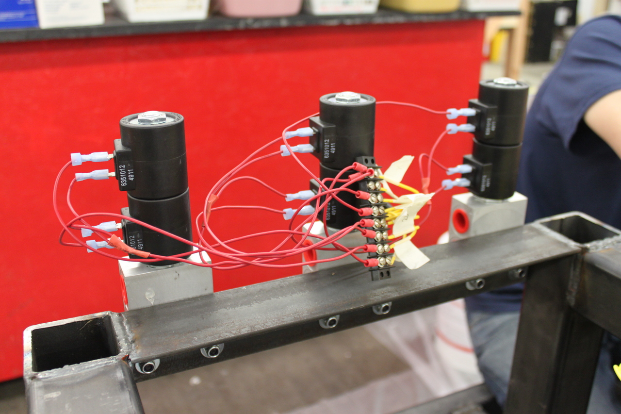
Our control of the proportional valves for the test amounted to a box of switches attached to each of the valves, powered off of a current-controlled power supply. The more current you push into the valves, the more hydraulic flow the valves allow – you can check out the HydraForce valves we’re using here. We had no idea what current settings would work for the robot, which is why you see the robot start moving really quickly at the start of the film and then move in a much more controlled fashion later on.
Check out our gallery of hydraulic assembly pictures below for more details on how we built this thing!
Installing and wiring our HydraForce proportional valves
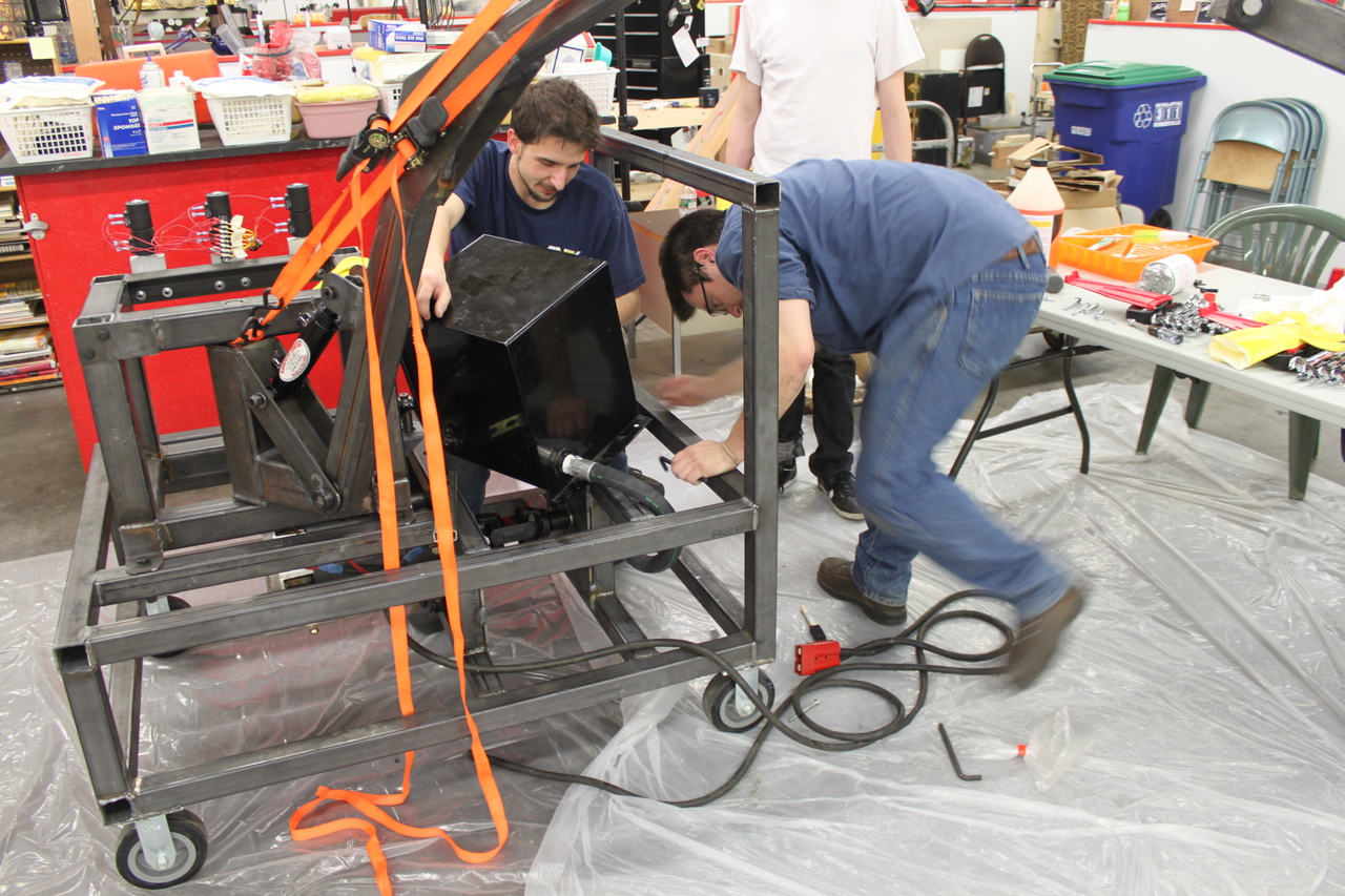
Dan and Mike installing the reservoir and attaching pump supply lines.
Spark and Andy assembly NPT fittings onto our filter
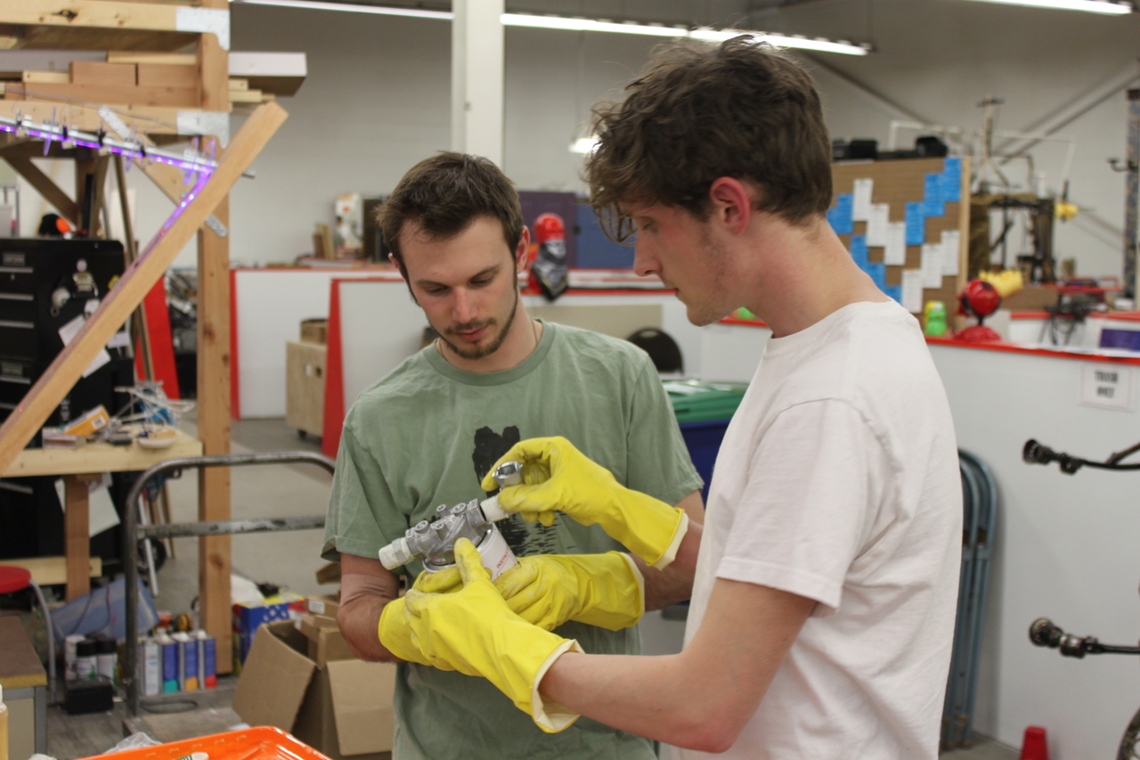
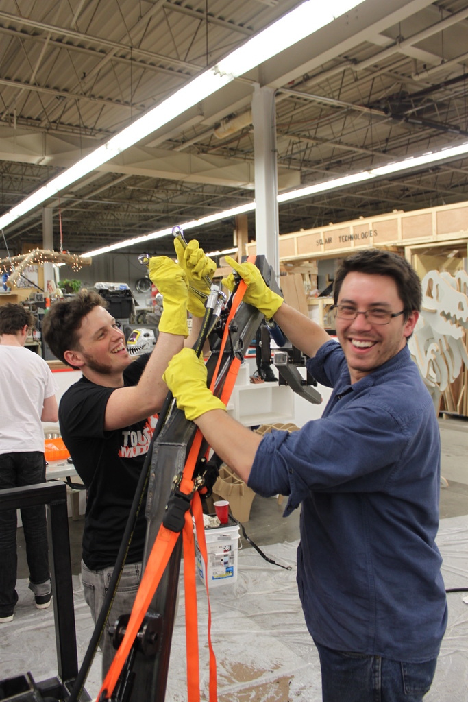
Mike, Mac, and Spark wrestling with our relief valve assembly
Dan and Mike assembling the pressure lines onto our proportional valves
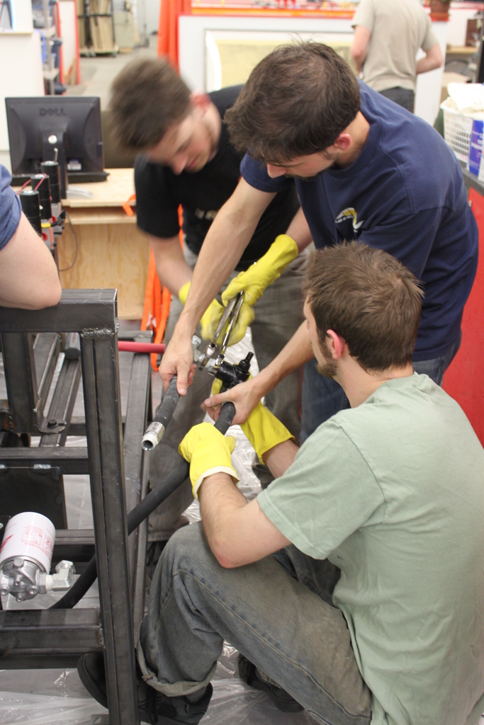
Mac and Dan assembling hydraulic lines onto the knee piston
That’s all for now. We’ll get some more videos once the electrical and controls team wrestles the mechanical system into something that’s much more behaved!
Yesterday, I presented on the basics of hydraulic system assembly. While technically only the mechanical team would have to worry about such things, we present basic lessons to the group so everyone is on the same page. After that, the group split up, with the mechanical team going out to assemble the parts we had and the controls and electrical group discussing next steps to controlling the Leg Cart.
The mechanical team took all the parts that we had been slaving over for the past month and put them together in our first fit-up. Even though not all of the parts were done, or all of the features machined or welded in, this let us develop a list of to-dos to keep track of and fix before the final assembly this weekend. It also let us get a sense of how big the cart and leg really were… we’re both horrified and really excited to see the cart paddling itself around Artisan’s Asylum in the near future. Without further ado, I encourage you to check out the pictures of the fit-up below!
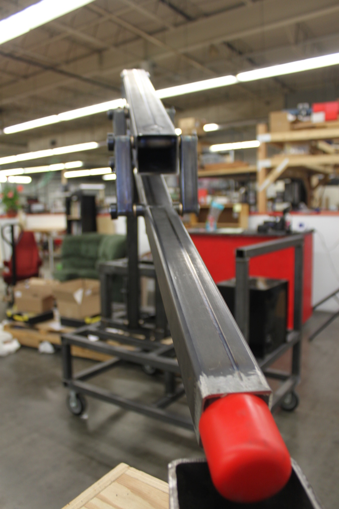
End-on view of the leg
The compliant mechanism for ground contact detection
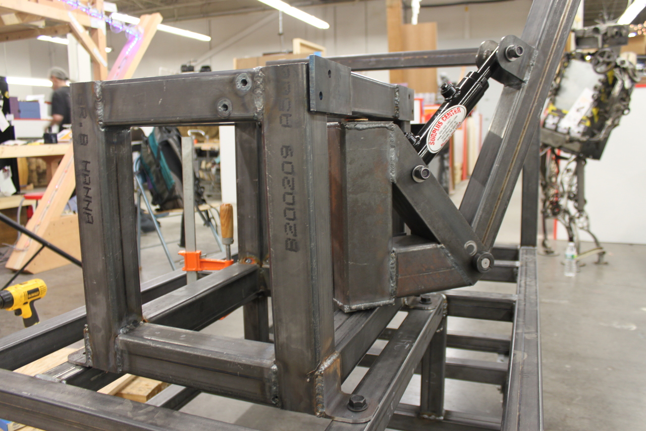
The base weldment to hold the arm
A third view of the fit-up
Another view of the fit-up
The fit-up Leg Cart
Just a reminder, the test leg is a roughly half-scale prototype we’re using to characterize the building blocks of our system. The leg isn’t anywhere close to the final design, it’s just a quick test system we could produce relatively quickly. The cart will hold a hydraulic power system in its base, consisting of a loaner 100-horsepower electric motor, our hydraulic pump, the fluid reservoir and all of other hydraulic system components. As if the system weren’t dangerous enough, we’re running the electric motor off of Adam Bercu’s electric motor cycle battery. Woohoo!
Also, in other news, we had our first team photo after the fit-up! Check it out here:
The Project Hexapod Team
Stay tuned for updates after this weekend, when we finish the mechanical assembly of the cart, start the hydraulic system assembly, and with any luck, hand the cart over to the electrical and control teams.
We came to a major decision this past week – the 2,500 pound, 135 horsepower, propane-fueled, hydraulically powered hexapod robot will be named… Stompy.
(It was a close thing, to be sure. We were split 10 to 8 between Stompy and Fluffy. Stompy seemed more unique and somehow more appropriate, though).
Today’s class was largely a workday. Dan gave a presentation on an introduction to controls systems and, specifically, the choices we’ve made thus far to ensure robust control of the hexapod. The controls group then chugged away at the Leg Cart simulation, while the mechanical group hit up the welding shop for a blitz of manufacturing. I think/hope we’re about a week away from assembling the full Cart, but we’ll see how it goes this weekend.
One big thing that got done – I finished the first round of concept art for the project. Given the parameters we’ve been working so far, the design techniques we’re aiming for, and the major components we’ve selected, I give you a first glimpse at Stompy:
Why? Because we can.
Note the two seats side by side. This is no solo ride.
You may be confused as to how large this robot is. The distance between the centers of the two middle legs, folks, is currently 17 feet. That’s about a lane of traffic… and a half. The bottom of the frame is over 6 feet off the ground. To give you an idea of how big that really is, check out this comparison to a shoddily rendered version of my car.
Well, we just wrapped up our second class session. We kept lecture time pretty short – we only did a brief introductory presentation on steel weldments (which you can check out here) and reviewed a couple of homework assignments from the first class – and then spent most of the class on (a) prepping the controls team to work with the upcoming Leg Cart simulation and (b) coordinating the mechanical team’s build progress. James or Dan will post some simulation videos soon, but in the meantime I thought I’d show off some of the mechanical work.
To get started, let’s review the hardware we bought before class, starting with…
Our "new", 135 HP Toyota 2F engineThe pump and driveshaft that match the engine
One of the sets of decisions we made as instructors early on was deciding on the powerplant. We needed something that provided sufficient power to provide hydraulic fluid for a 1-2 ton robot, that was (a) robust, (b) relatively affordable, and (c) as off-the-shelf as possible. We decided to rip the hydraulic powerplant out of a forklift (specifically, a Toyota FGC-45 from 1991) and repurpose it. The net result is that we have a 135 horsepower, propane-powered powerplant that produces upwards of 35 gallons per minute of hydraulic fluid at 2,500 psi. The fact that it’s propane fired means the robot can operate for brief periods indoors, and also means that we can swap industrial-grade fuel tanks good for 6 hours of runtime without having to custom build or fill any of the fuel system components.
So that’s what we have – what we’re working on now is making the Leg Cart, our prototype hydraulics platform. The idea here is to make a platform on “rails” (i.e., only able to move in one dimension) that has a single leg and a hydraulic powerplant on board (we’re borrowing the pump from our full system and running it off of a giant electric motor). This will be the students’ introduction to hydraulic systems, so we’re building something small (relative to the final system – the cart will still be 600 pounds…) at first so we can screw up and figure out what we’re doing. Without further ado, here’s the progress we made on the cart chassis in the past week:
The Leg Cart chassis as of 4/26/2012
Spark and Mac have been working hard at it for the past week or two – good work guys! Next up, we have the base weldment for the arm pivot:
Base weldment progress as of 4/26/2012
Adam and Andy teamed up to work on this over the past week. Unfortunately, some material was backordered, but we’ll be resolving that shortly.
Joel, Joe, Mike and Jona are all working on parts that are heavy on machining and low on welding, so we’ll see updates from them a bit later on in the process.
That’s it for now. Keep an eye out for an update on simulations!
OK! The blog is up, we just had our second class session, metal’s being cut, and simulations are being written. We’re off to a hell of a start, and now it’s time to tell the world.
We are Project Hexapod. We’re a team of 19 people who are trying to pull off the highly improbable; building a giant (1-2 ton, 15 foot diameter), rideable 6-legged hydraulic robot. We’re not some robotics company, and we’re not working off of some big grant or another. We’re tackling this problem in a whole new way; we’re a class based out of Artisan’s Asylum, a community workshop with all the fabrication facilities we could possibly need, where 15 students are learning how to build robots from 3 industry roboticists from Barrett Technologies and other local robotics companies, and 1 national champion Battlebots builder as a teaching assistant.
As I mentioned, we just had our second class session. The class officially kicked off on April 17th, though me, James and Dan have been working on the system-level design for the past 6 months to make sure the whole thing was possible. We’re going to push to make this project as open-source, publicly engaging and widely available as possible, so be sure to check this blog for presentations, source code, design documentation, the works.
And thus, without further ado, let’s talk classes!
Class 1: What Did We Get Ourselves Into?
Our first class was all about shock, awe, and expectation management. We introduced ourselves, the scope of the project, the exercises and design steps we would be taking to achieve our goals, and then did a quick introduction to hydraulic systems to get everyone on the same page. Once all of the lecturing was done, we broke up into a controls team and a mechanical team; the controls team busied themselves in setting up a simulation environment that James and Dan developed for the class, and the mechanical team got launched on making and welding parts together for the Leg Cart (more on that in a bit). You can check out our introductory presentation here: Rideable Hexapod Intro 2012-04-17
After the introductory presentation, I presented an introduction to hydraulic systems. If you’ve never used hydraulics before, I suggest checking this out – they’re a fascinating power transmission technology widely used in farming equipment, earthmoving equipment and high end robots like BigDog, but are almost nonexistent in the hobby/amateur robotics world. There’s certainly a steep learning curve to hydraulics, but hydraulic systems are awesome and you should learn how to use them. Learn more about them with us here: Intro to Hydraulics 2012-04-17 (Warning! There is one gory image of a hand after it’s been hit by a hydraulic leak, which may be NSFW)
Once all the presentations were over, it was time to start work on the Leg Cart! Also known as the Land Barge, Land Gondola, single leg prototype, that-which-cannot-be-stored-easily, and generally-terrible-idea. The mechanical team got a giant cut list to work on for the next two weeks, and the controls team got introductory exercises in our custom simulation environment.
The Leg Cart
The cart is a giant, 600 pound monstrosity with a half-scale hydraulic leg sticking out the side, a hydraulic power system (using a 100 pound field-wound electric motor attached to our hydraulic pump), all on four fixed casters (yeah… you heard us… we’re going full stupid here). The idea here is to have the students get familiar with working and welding steel, assemble a functional hydraulics system for the first time, wire real hardware with feedback sensors and a computational platform, wrap feedback loops around sensors and the hodge-podge hydraulics system we’ve assembled, and then control custom hydraulics hardware in closed-loop forward and inverse kinematics. If everything goes according to plan, the cart will be able to paddle its way up and down a section of the shop aisle.
OK. That’s the update for class 1. Stay tuned for the next class update, where we post some pictures about our progress on the Leg Cart and maybe a simulation video or two!