Stompy simulations, full scale test leg out for quote!

Ladies, Gentlemen, Undecided and Robots –

It’s been two weeks since our last update and the team has been cranking away…

We’ve been iterating through a design spiral trying to hammer out a leg design. Starting with rough estimates of masses and link lengths, the controls team figures out what kind of joint torques and range of motion would be required to meet the design goals and passes this information back the the mechanical team. The mechanical team takes this data to come up with a leg design, which they then run through FEA to determine the viability of the design. If they think it’s a viable design, they pass its critical parameters (masses, force/torque limits, actuator placements) back to the controls group, who plug the new parameters in to the simulation and give feedback back to the mechanical group, who modify the leg design, etc.

This is a labor intensive cycle that we’ve run through several times in the past 2 weeks and have come up with leg designs that we think will work. Without further ado, our first glimpse of Stompy walking…

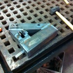
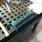
These legs are designed to be cut from sheet steel on a water jet. The waterjet cuts slots and tabs so the pieces of the structural elements will slot together like Ikea furniture. We will then weld over all the tabs to make extremely strong leg pieces with minimal machining on our part.
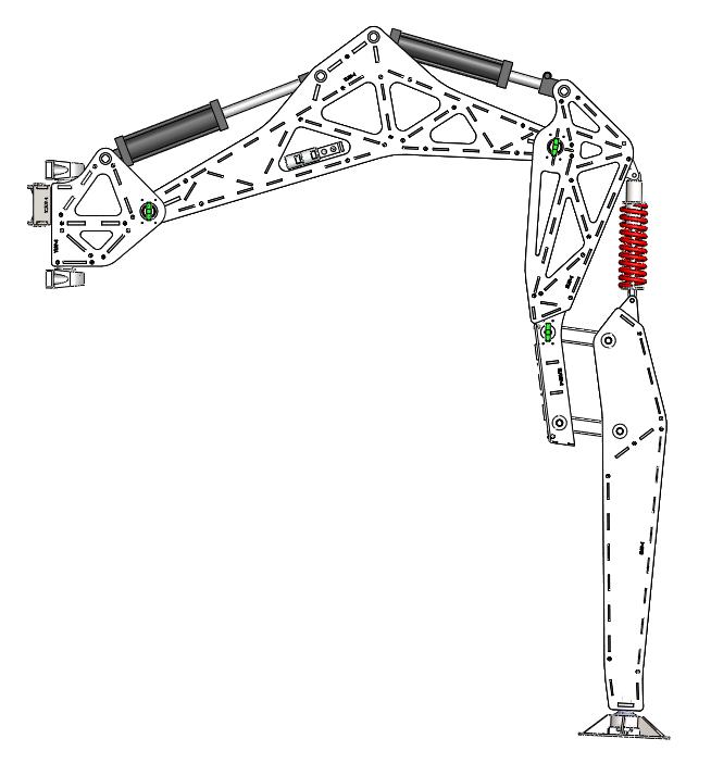
This is what our full-size prototype leg will look like extended.

The torques on these legs is tremendous… at the hip the torque is on the order of 14,000 foot pounds. The torques decrease in magnitude as you go further out on the leg, allowing for lighter construction. The yaw link (the little chunk of metal between the body and the thigh) is made of thicker sheet steel than the rest and ends up weighing about 70lbs. The thigh link is around 200lbs without the actuator attached. One of the comprimises we had to make in the design spiral was to shorten the legs… we simply couldn’t achieve the safety factors we wanted with the legs spread out as far as they were in the original concept art.

The prototype leg is out for quote at local machine shops, as is the next version of electronics, about which there will be a post soon. Also expect to see a Gimpy update!

~James

Gimpy’s First Controlled Movements

Ladies, gentlemen, undecided, and robots,

First I am pleased to announce that the Leg Cart has a name. It is now known as Gimpy.

We have been working hard trying to move Gimpy in a controlled way. “Controlled” here has a specific meaning… we mean we are controlling the joint with electronic feedback through a computer. If you’re new to control theory, the image below should give you an overview of what we’re trying to do.


Overall we are making progress and have demonstrated good closed-loop position control of our joints. We also exposed some system-level problems and snapped an actuator mount…


We have done additional tests since filming the video, but a combination of hardware problems (see our last post about ) has eaten most of our development time.

The knee joint in particular is prone to accumulating air and developing massive levels of uncontrollable backlash. We hypothesize that one of the reasons for this is that the knee actuator is the highest point in our hydraulic system, so when our system is unpowered bubbles will try to rise in to the knee. We are going to experiment with raising the pressure on the return lines and co-locating the knee control valve with the actuator, both of which could help with the air problems.

The whole reason we built the test leg was to learn the ‘gotchas’ of our component selection. These setbacks are expected and welcome, because now we can avoid them on the hexapod proper.

Long live Stompy.
~James

Sunday Build Blitz was Great!

Today (Sunday May 6) was an epic build session at the Asylum… work started at 10am and finished around 9pm.  The shop was bustling with activity… machining, grinding, welding, soldering… the fabrication team really came together and was firing on all cylinders.

Almost all mechanical parts have been fabricated for the leg on cart.  Electrically we have working valve control and joint angle feedback.  Tomorrow (Monday) will be a flurry of assembly.

Just a reminder, the test leg is a roughly half-scale leg we’re using to characterize the building blocks of our system.


Controls Assignment 2 Solution

The controls team pulled it together at the last minute and submitted a solution to the problem of pushing the leg cart in a smooth, controlled fashion.  “Controlled” in this context means that it can’t lift itself off the ground and foot slippage has to be minimal.

The control code here is 100% student written, from the joint controllers to the kinematics to the trajectory generation.  Go team!

For reference, the dots are 1m apart.  The simulation makes it clear that we really need to watch out for reaction torques about the yaw axis (note that the whole cart twists itself… this is with a relatively realistic friction coefficient on the wheels).  We will probably want to look at this more closely before putting anything on hardware.

Beware the Barge

I built a model of the leg cart/leg test stand in our simulation environment.  Leg dimensions, masses, ranges of motion and actuator force limits are all in the model.

On the meatspace implementation the inputs to the system will be valve commands, which roughly correlate to flow rates.  In an attempt to model this, we present actuator linear rates as the inputs to the model.

This week we assigned the controls team the task of controlling the cart and making it row itself along in a straight, controlled line.  We’ve got groups working on joint level control, forward kinematics, inverse kinematics, trajectory generation and the nebulous “high level”.  As a starting point I put together a little demo with the leg cart rowing itself along very poorly:


For reference, the cart weighs about 600 pounds and the pins weigh about 200 pounds and are 6 feet tall. When this thing exists in real life, we will have to be very careful…  More videos next week when the student solution starts coming together!

~James

Welcome to the blog

Hello world!  The first class is nearly upon us.  On Tuesday, April 17 2012 we will be having our first full class meeting.  The instructors have been working overtime for the past few months roughing out system level design.  We are putting it all together in to a presentation, I will bloggify the summary once we are done with the presentation.  Oh boy!

-James