Hello all, M@ here with an in-depth look at what exactly goes into assembling an unbelievable giant hexapod robot. Normally I do controls (software) and document our efforts, but today I’m helping with the physical building process.
Before I get started, let me first say what a great honor it is to have had such an amazing Kickstarter response, your faith in our project blows me away. We’re just as excited about this project as you are… it’s incredible… it’s going to be great!
Today we’re going to be looking at the thigh link. As it was delivered to us from the waterjet company our leg looked like:
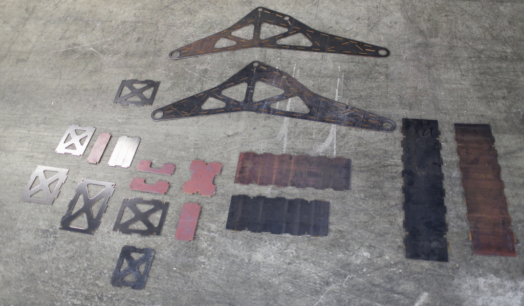 …Obviously it’s in need of some assembly :-D. Lets look at some of the features that will help us assemble the link. I’d like to call attention to two key features on all of the steel plates: the plus-signs and the tabs.
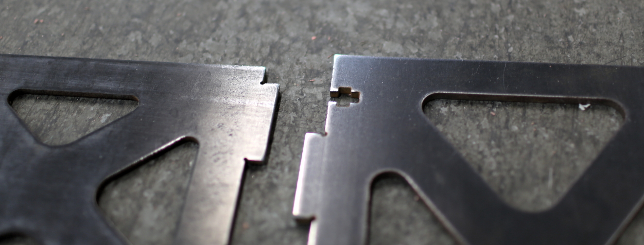
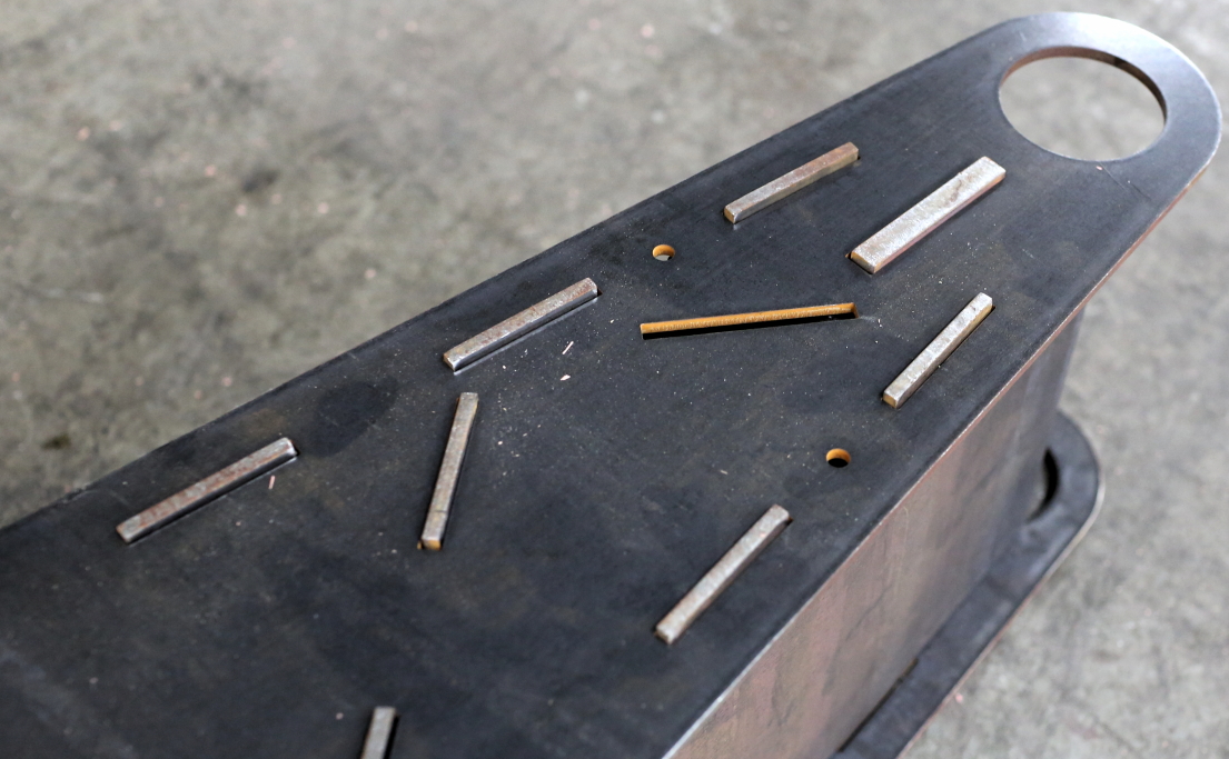
Note the plus-sign cut into the plate on the right. The idea here is that eventually these plates are going to be welded together, but while we are doing that welding something is going to have to hold the plates in place (something will have to act as a jig). To simplify construction, we incorporated the jig into our plate design; we can simply insert a square nut into the horizontal line of the plus, and then sink a screw through the other axis.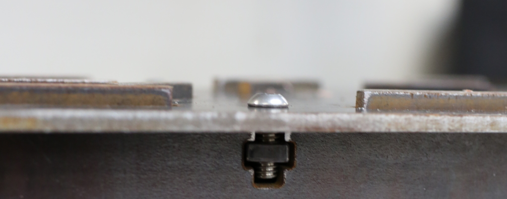
Additionally, each plate has tabs along the top and bottom edges, and some plates have slots. The tabs fit into the slots and the two get welded together. Having the tabs makes assembly roughly a bajillion (technical term) times easier. You’ll hear more about these tabs soon (great idea though they were, there is room to improve… learn from our mistakes!).
Anyway, on with the assembly. The goal of this phase of assembly is to arrange the pieces so that they can be welded into a final thigh link. It sounds more complicated than it is, if you’ve ever successfully assembled Ikea furniture you’re overqualified. Just line up the tabs of each piece with the slots of the thigh-sides, as in:
If you’re following along, just ignore the 3/8ths pieces for now, we’ll put them in later. If you’re building something so beastly as to require 3/8ths for the side panels: A) sweeeet! drop me a line, I’d love to hear about it and B) you might as well set up the vertical 3/8ths plates now, they should stand up fine.
In the spirit of hoping that you’ll learn from our mistakes, check out: As you can see, both plates have the same holes and the same tabs and yet are ever so slightly different sizes. In my humble opinion, this is a bug in our initial design. The problem is that during assembly it’s very likely that one plate will end up where the other is intended which could lead to forces not being transferred correctly. If you find yourself designing a robot so serious that it requires welding, learn from our initial mistakes, design the tabs such that it is impossible to fit the plates together in the wrong way (vary the sizes and whatnot). If you do that then the assembly step is simply a jig-saw puzzle (no need to consult the CAD model).
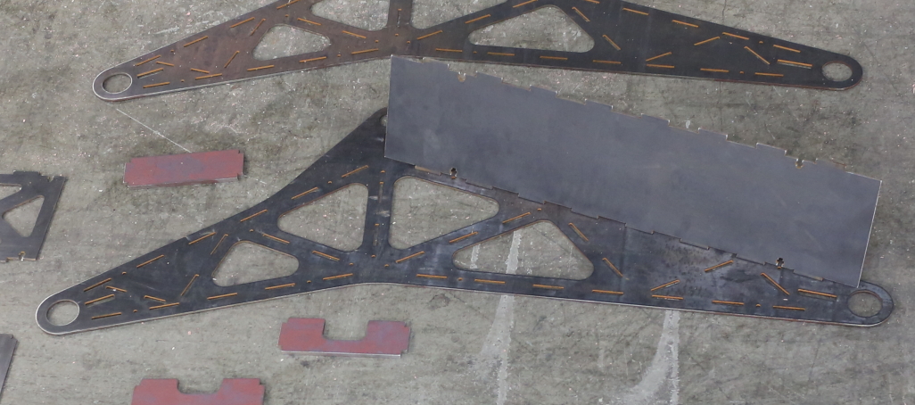
Pretty soon you should find yourself at a state that looks rather like this picture.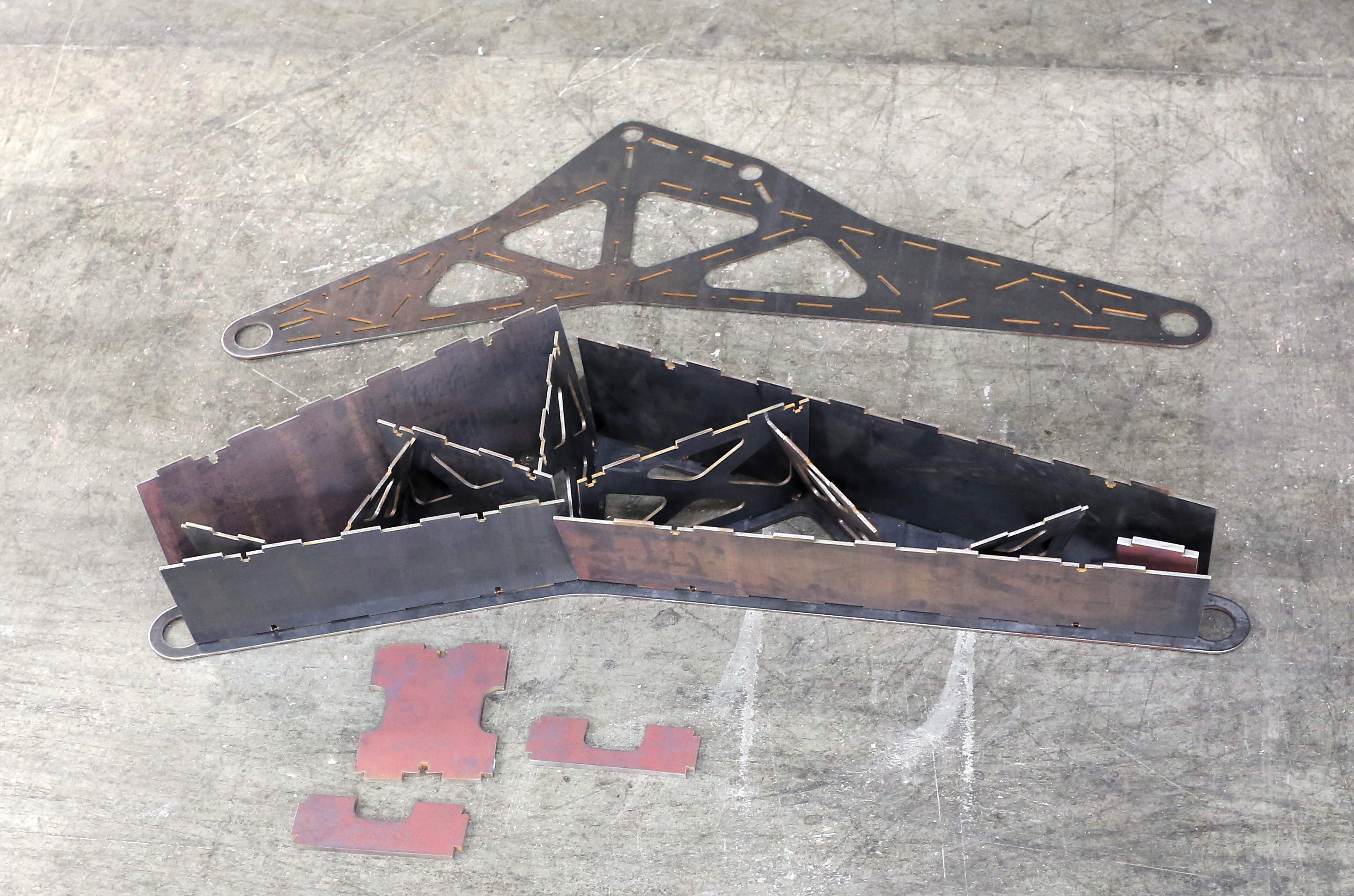 All the 1/4″ vertical pieces are loosely in there, the 3/8″ pieces are waiting for a smarter time to be inserted, and there is a top plate that looks like it will be hard to set into place. Begin by slotting the plates that are nearest the middle of the link, and then working outwards. The reason for this is that inserting subsequent plates only requires lifting the ends of the side-plate, so the parts that have been slotted already are unlikely to fall loose. When all goes well you should see something like:
Now it’s time to sink a bunch of machine screws into square nuts held by the clever plus-sign shapes that we designed into the plates. Again, it’s like assembling something from Ikea. Attach as many plates as possible to the top plate. When you’re all done it will look something like
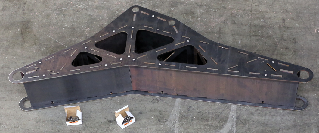
At this point, get a friend to help you flip the link over, it’s heavy and risking throwing out your back is dumb. I chose my friend (and fellow hexapoder) Jona. Once you’ve got it over, install whatever remaining plates there are, and then machine-screw on the other side-plate.
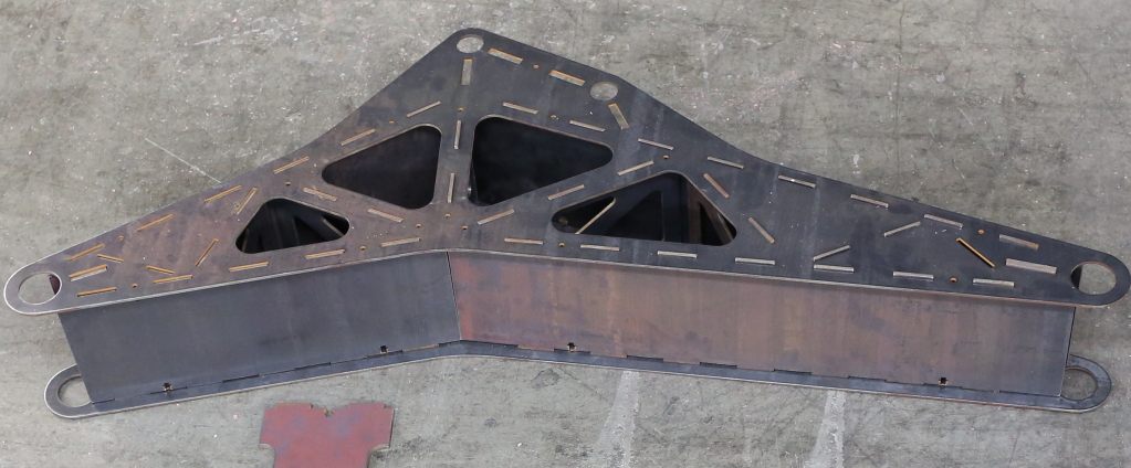
 Pat yourself on the back. At this point you’ve got a link ready to hand off to the welding team… or do you? It wasn’t obvious at first (even to us), but that initial collection of parts wasn’t quite complete… see if you notice something missing in this picture. As it turns out the company we contracted to do our waterjetting forgot one plate! Oh noes! But that’s ok, we all make mistakes, the completed part is on the way :-).
Of course, not all of our links were missing plates, check out the upper shin link (which underwent the same process), all welded and beautimous! 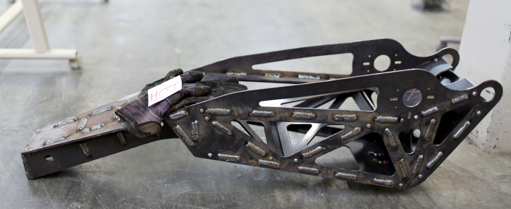
Much love, and thanks again for the response on kickstarter, it’s been an inspiration! As I write this I’m covered in steel filings and cooling fluid (I was being lathe-y after I finished this post up)… I’m going to go take a shower.
–M@
Please submit that top image to http://thingsorganizedneatly.tumblr.com/. They have too few submissions of giant robots awaiting assembly!
@Jason What an interesting photo blog, I’ve submitted it. No telling if it’s neat enough to make the cut, but we’ll see.