Hey everyone; it’s been a while.
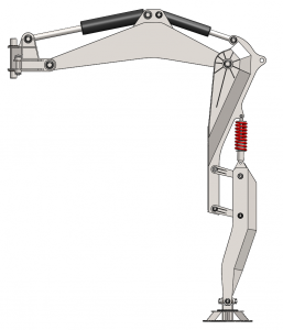
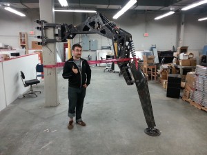
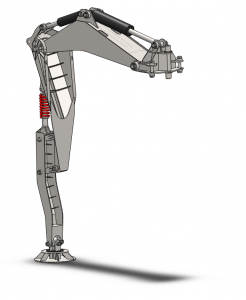
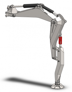
We’re kicking off our triumphant return to communication with a recap of what’s been going on with the Hexapod design process. Today’s recap topic is the most visible change to date: the new leg design.

When the proto-leg was designed, it was intended for two purposes:
- To act as a testbed for electronic points, hydraulic plumbing, and other systems mounted to the legs.
- To give the team insight into the process for designing and assembling a hydraulic system at this scale.
This was largely a success. During assembly and testing of the proto-leg, we identified a list of challenges (you may remember the series of posts on tuning the system to reduce yaw oscillation, as well as the process updates on mounting hydraulics and upgrading cylinders). There was also discussion about tolerancing to minimize backlash, lessons learned about welding, and many other things which tied into the main difficulty with the leg, which was assembly, assembly, assembly. Proto-leg, you were no piece of IKEA furniture to easily snap together, but you’ve served us well. We’ll cherish the memories.

Once both the prototype leg and the hydraulic power unit came together, the team turned to designing a new leg. Given the list of challenges we identified, we ideated and evaluated a series of designs to combat any assembly and runtime difficulties. Then, sticking to our original heuristic of maximizing leg strength vs. weight, we began to spec componentry and make CAD models of the production legs. To speed up this process, we chose a design which allows us to optimize our toolchain by including better FEA (finite element analysis), earlier on.
In the end, we chose to spend money to save time; by choosing to use spherical bearings on all of our joints. Spherical bearings at either side of a joint allow for the pin passing through to self-align, saving the team both tolerancing woes and removing the need for one of the last favorite parts of the proto-leg assembly process: using a 10 inch reamer to account for the misalignment caused by deformation resulting from welding. The process is as uncomfortable as it sounds, in case you were wondering.
A huge shout out is in order to our newest sponsor, AST bearings, for giving us a great deal on some extremely nice spherical plain bearings. The bearings we got were so nice that we’re now using SPBs not only in joints, but also for the hydraulic cylinder attachment points, as well as the shock mounts for the compliant link. Thank you, AST, for supporting supporting open-source robotics!

Once this design was set, we began to optimize the leg for torsional stiffness and ease of assembly. The resulting design is wider than the original leg, but not significantly heavier, due in part to the removal of the internal bracing on the knee and thigh links (which we found wasn’t doing much). This allows us to mount a larger, stronger thigh actuator to better allow the robot to stand. We’re also now able to put in provisions for both a single push-pull, or two antagonistic cylinders on the yaw link, giving us multiple avenues for solving the yaw oscillation issues in hardware (in addition to our software solution). In lieu of bracing, the leg takes its strength from the much larger surface area of the steel on the sides of the leg, which acts as a load-bearing skin.
Back to assembly: the new leg design adjusts tolerances on the slots and tabs of the sheet plate to suit the characteristics of our plasma cutter, so the production leg can be jigged up for welding faster than the proto-leg (we’ll tell you how welding the leg goes when we try it). Finally, the new leg just looks cooler. Sci-fi nerds take note: the increasing resemblance to Protoss Dragoons, however unintentional, is considered a plus.

Thanks for reading! For those among you who saw something referenced, but not explained, feel free to asks questions in the comments, and keep your eyes open for our follow-up posts on FEA/mechanical design process, the new electronics for the legs, and hydraulic topology and installation.

Hi,
We are three students of Mechanical Engineering of University of Florence.We have to prepare for an exam.This examination is formed from a written part and by a project.For the project we want to design a part of hexapod:one arm.We want to ask you if you can provide us the static scheme and cad model for the single arm.Thank you for the attention.
Yours faithfully,
Francesco,Lorenzo,Federico
Hi!
We’ll try to publish all our CAD in a useful place soon. In the meantime, you can grab copies of the leg pieces from https://github.com/braingram/stompy_simulation/tree/master/gazebo/models/stompy_leg
-Spark
Hey!
I am in the process of designing a HEAVY legged hexapod (15 tonnes – eeep) but am unsure on the theory behind the legs and how I know they’ll all be able to withstand the weight. Do you have any calculations or theory behind how you knew your legs wouldn’t buckle?
Thanks!
We used an iterative design process of modeling the legs in SolidWorks and running Finite Element Analysis to determine whether they would hold up to the weight of the robot. Good luck!