Hello everyone!
Apologies for the lapse in our updating – we’ve been in three solid weeks of Systems Integration Hell with the Leg Cart, trying to get our hydraulic system to achieve good position control on the hydraulic actuators. Because we’re purposefully developing with really low-end technology, we keep running into components that just don’t cut it – so slowly but surely, as we replace the components that just don’t cut it and upgrade the system, we’re building up a solid hydraulic powerplant. James will post a video of the position control we’ve managed so far a little later, but for now I want to talk about our hydraulic system.
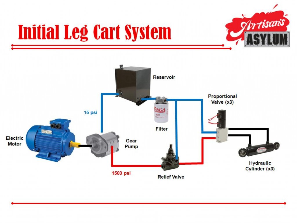
So, this was our first pass at a layout for a low-cost (relatively – it still cost between $1,500 and $2,000 for all the components you see here), prototype hydraulic powerplant:

The central idea was to use a giant electric motor to spin up a gear pump while we work on getting our propane powerplant up and running. Because a gear pump displaces a fixed amount of fluid every rotation (and because there’s no guarantee that any pistons are moving while the motor is on), that fluid needs to go somewhere. The standard answer for a low-cost hydraulic system is to insert a relief valve on the pressure line; the relief valve allows pressure to build up to a set point, then the valve opens and dumps any remaining fluid into another set of lines. In this case, we dumped all of our remaining fluid into our return pressure line. Because the line was connected directly to our reservoir, the return fluid was at atmospheric pressure. We used the following components to create this system:
- A MT2119 series-wound DC motor
- A Toyota-branded pump variant of a Parker PGP 333 9112 357 (which is the exact replacement pump for the FGC-45 forklift)
- A RV-2H Relief Valve
- A FA-1200-10 Return Filter
- A 9.8-Gallon Reservoir
- SP10-47C-8T-N-12-DS Electroproportional Valves
- Surplus Center brand pistons for pitch, yaw and knee actuation
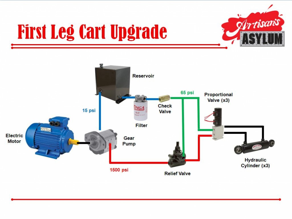
This version of the Leg Cart system didn’t last for too long. The reservoir kept the return pressure at atmospheric pressure, and that meant that the knee cylinder (which was above the oil level in the reservoir) was constantly full of air – we’re talking a couple of inches of piston movement worth of air, at all times. Once we understood exactly how much air was in the lines, we knew we needed to increase the pressure on the return side so that return fluid would force its way through the entire system. We did that by modifying our hydraulic system like this:

We added a check valve that had a cracking pressure of 65 psi to the return line, right before the filter. This meant that no return fluid would flow into the reservoir unless the return line was at or above 65 psi. While adding a check valve to increase return line pressure isn’t something I had seen done before, I figured it might work, and would be the cheapest solution.
This system successfully removed a lot (though not all) of the air from our lines. When we ran our joints through their range of motion, they more-or-less bled themselves (with the exception of the problematic knee joint – more on that later) by forcing any air into the return line system after the pistons cycled through their range of motion. Then, however, we ran into a whole other problem… our motor and pump started heating up so much that they couldn’t be touched for longer than a second or two after only very brief runs. In addition, our high pressure started dropping after only a few minutes of runtime. In any hydraulic system, if things are getting really hot really fast, and pressure is dropping in a pressure regulated circuit, something is very wrong.
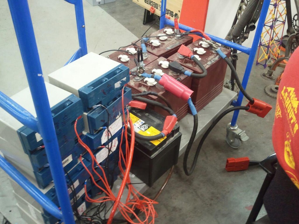
Let’s take a quick, related detour. One thing I haven’t talked about yet is our electrical system. If you read up on our MT2119 series-wound DC motor, you may have noticed that it can reach around 100 horsepower at peak load. At 12 volts (what we’ve been running it at thus far, to keep total flow down to appropriate levels for a single leg) and 1500 psi, the motor draws over 330 amps. In our first video, you saw us run the whole platform off of two deep cycle batteries; these lasted for less than 10 minutes of total runtime. To give ourselves more runtime, we created… a monstrosity:

What you see there are 4 red deep cycle 6-volt batteries, 2 black deep-cycle 12-volt batteries, and 12 SLA motorcycle batteries, all wired together at 12 volts. All told, they represent something like 500 to 600 amp-hours of (relatively) safe electrical capacity. The wires are all sized appropriately, and the only alligator clips that are involved are attached to a 10-amp battery charger.
What we discovered after about a week of having no idea what was going on was that this giant battery pack was capable of providing enough power to supply 1500 psi when it was fully charged… and then wasn’t able to supply the necessary torque to maintain 1500 psi after about 15 minutes of runtime. This meant that the motor was turning our gear pump, but since the pressure wasn’t high enough to crack our relief valve, the fluid was getting stuck in our dead-end high pressure line and our gear pump was pumping fluid back through its own internal leakage pathways. This turned into a mechanical thermal runaway condition, where the more we pumped, the hotter the pump got, the hotter the trapped fluid got, the thinner the fluid got due to temperature increases, the more fluid the pump pumped, and so on and so forth.
OK. We successfully diagnosed the (incredibly bad) problem – now to do something about it. We tried adjusting the RV-2H Relief Valve we bought, only to realize it was… a total piece of crap. No amount of turning would adjust pressure up or down from the factory setting. We threw it out in disgust and bought ourselves a Parker RPL-16-A, rated for the flow of the final robot and adjustable from 500 to 5,000 psi. It arrived, our tests were much more successful, pressure was maintained at 1,000 psi throughout hours of testing, and the pump stayed cool.
So here’s where we stand now:
- The system is finally running predictably and relatively cool
- We believe our pump seals are damaged due to the thermal runaway condition and the fact that the pump reverses dramatically when we shut the system off (because there’s no check valve on its output, and the remaining hydraulic pressure spins it backwards)
- We believe we’re sucking in air through the damaged pump seals
- We believe the check valve we used to increase the pressure of the return line is sticking closed and interrupting the return flow, leading to poor position control
- We’re still noticing significant amounts of air in the knee actuator, and think it’s due to the fact that we can’t bleed the cylinder well because the hoses running to it are too long (and potentially some damage from installation)
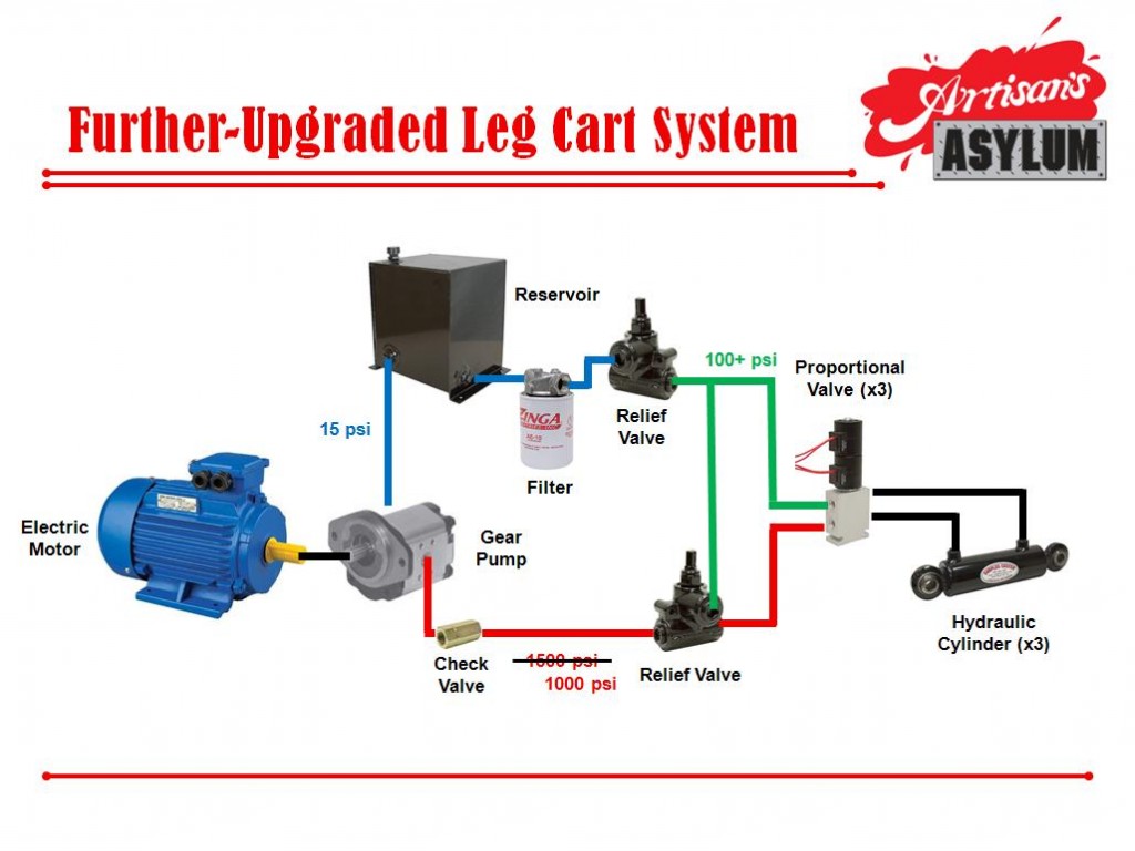
So, all that being considered, we’re upgrading the Leg Cart to the following system:

We’re changing the following:
- We’re swapping in a brand new Prince SP25 gear pump, which has an identical displacement per revolution, mounting plate, spline shaft, direction of spin, and rating as our allegedly damaged Parker pump. This unit has SAE fitting outputs instead of face seal fittings.
- We’re removing as many NPT and face seal fittings from our supply and pressure lines as we can to decrease the possibility that air is entering through them.
- We’re adding a low-cracking-pressure check valve immediately after the pressure output of the pump, to prevent pump backspin.
- We’re adding a low pressure adjustable relief valve to the return line to (hopefully) allow for better flow control on the return side of the system.
- We’re adding a low pressure dial gauge to the return line to see if there are actually pressure fluctuations, and if they correspond to hiccups in our PID control.
- We’re moving the knee piston proportional valve to the thigh itself, so that the lines from it to the piston are very short. Hopefully, this will allow the piston to self-bleed much more than before, and hopefully reduce the amount of air trapped in it on a regular basis.
Whew. Fingers crossed that this upgrade solidifies our hydraulic system – it’s been a pretty torturous couple of weeks to get to this point.
Keep an eye out for a post from James with a video and discussion of our latest position control efforts!
-Gui