Hello everyone! We want to take a moment and catch all of you up with how the build process has been developing over the past few months. As a quick note – we’re most active on Facebook, so if you’d like weekly photo albums of what we’ve been up to, we suggest “Liking” us there!
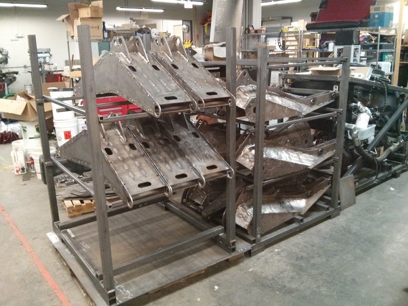
In our last post, you saw us put out a call for new members; we’re happy to report that we accepted 8 new people onto the team, and we’ve all been putting our heads down and cranking on steel fabrication. We’ve been building our way up the robot’s leg in parallel (i.e., we’re building all of one type of part before moving on to the next) from the calves, to the knees, to the thighs, and we’re on the cusp of starting the hip – the final link in the chain. We’re building 8 copies of each piece, with the hope that in the best case, we have two spares, and in the worst case, we can mess up 2 parts of each type without affecting the overall construction schedule. After the hips are done, we’ll start the chassis build in earnest, and then we’ll be ready for final assembly! We’re going to take a moment and step through what our build process has looked like, and how it’s evolved as we’ve gotten better at large-scale steel fabrication.
All of our leg parts are made out of pieces cut on the CNC plasma cutter we assembled at Artisan’s Asylum. The plasma cutter has a couple of big advantages – it has very low running costs, it’s extremely fast, and it’s available on an as-needed basis. Check out this album for some shots of the plasma cutter in action, and a look at what we have to do to move some of our heavier sheets around:
%%wppa%%
%%slide=13%%
The plasma cutter does have some distinct disadvantages, though – the biggest being that plasma cut parts require a lot of cleanup before they can be reliably welded together. The plasma cutting process creates what’s known as dross on the back side of cut parts. This is a thin, brittle, very hard layer of flash-frozen steel that usually has to be removed with grinders. We performed some initial experiments which indicated we couldn’t create reliable, clean welds if the dross and mill scale on our steel plates was still present, so we set up an assembly line of angle grinders to clean up all of our plates. After dozens of hours of grinding, we realized that we desperately needed another way to clean parts or we’d never finish; we then switched to pickling, a process where parts are dipped in vats of acid to remove impurities. We started with hydrochloric acid, and then quickly switched to citric acid due to safety and cost concerns. Check out the cleaning processes we’ve been through in this album:
%%wppa%%
%%slide=14%%
Once parts have been cut and cleaned, it’s time to assemble the pieces into cohesive links and weld them together. All of our links fit together like 3D jigsaw pieces; plates fit together with slots and tabs (check out our “Anatomy of a Thigh Link” post for an example section from our prototype leg), and square nuts and button head cap screws hold the plates together after they’ve been fit-up. This means that our leg sections are self-jigging and self-aligning, and require very little external tooling to fit together precisely. Once assembled with screws and square nuts, the links can be moved around for transportation and weld positioning. After assembling, we tack weld them in a specific order, plug weld sections together to increase the rigidity of the assembly, and finally weld all of the seams together to finish the parts.
%%wppa%%
%%slide=15%%
Once the leg sections are assembled and welded, it’s time to add joint bushings. In our prototype leg assembly, we made joint pivots and hydraulic cylinder pin joints with bronze bushings and carefully-aligned and welded steel cylinders that spanned the width of our leg sections. This style of design was incredibly time-consuming to weld accurately, and more often than not resulted in significant post-machining steps like hand reaming that gave relatively poor results across the width of our legs. We decided to cut down significantly on assembly time and fabrication time by switching from bronze bushings to self-aligning spherical bushings – that way, even if we were a little off during fabrication, jointed assemblies would still fit together relatively seamlessly. Check out this album of our process for making bushing bosses and welding them on to our assemblies accurately:
%%wppa%%
%%slide=16%%
All that said, we now have a full robot’s set of thighs, knees, calves, and compliant links welded together. Pieces still need some finishing work before they’re 100% done, but most of the link segments are there. Now, it’s time to move on to making hip sections and the chassis, so that we can start final assembly!

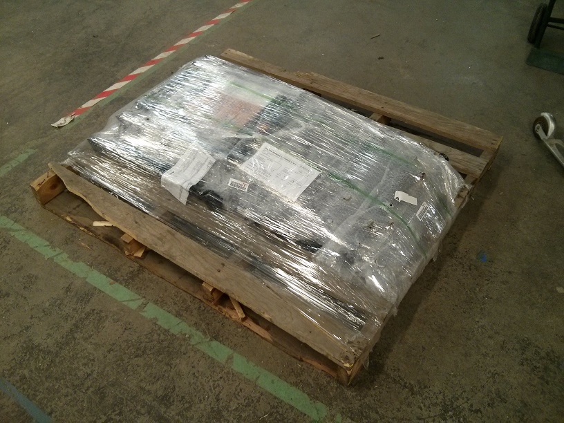
Also, one final bit of good news – we’ve received our custom cylinders from Dalton Hydraulics! We ordered these two months ago, and asked for a custom build so that we could have exactly the output ports we wanted on all cylinders (-08 SAE, to match our valves) and very tight tolerances on the cross tubes on the front and back of the cylinders so that we have as little backlash in our joints as possible.

That’s it for now – look for thigh links next, and the start of chassis construction!